Welcome to Laser Pointer Forums - discuss green laser pointers, blue laser pointers, and all types of lasers

LPF Donation via Stripe | LPF Donation - Other Methods

Links below open in new window

ArcticMyst Security by Avery

505 nm laser diode

reloader45

Active member
Joined
Mar 17, 2019
Messages
172
Points
28
Hello Rich,

the diameter of the beam expander thread is 11,44 mm. Normaly the outer diameter of a bolt is undersized. So my guess was 11,5*0,5 mm.


best regards

Edgar


Joined
Dec 15, 2014
Messages
6,782
Points
113
Hi, I had a special tap made for me custom, if the thread your replying to is 11.44 Its just .4 . When I thread an adapter or sink with this tap the BE threads are like butter perfect fit no wobble . .5 is just a tad too big, What ever works for you buddy.

Rich:)
 

reloader45

Active member
Joined
Mar 17, 2019
Messages
172
Points
28
Hello,

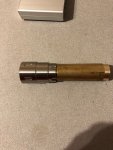
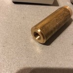
today I made a 11,5*0,5mm tap from tool steel. I had a test run in brass. The tap works in that material, although the grinding of the free angle of the cutter was handmade an a little bit poor.

The fit of the beam expander is not a snug fit, it is a little bit loose, but it works. So the tap could be a little bit smaler, maybe 11,4 mm is better.:)
The fine thread is hard to catch with my IPhone.

best regards

EdgarIMG_0123.jpgIMG_0122.jpg
 

reloader45

Active member
Joined
Mar 17, 2019
Messages
172
Points
28
Hello,

just visits the Sanwu homepage. They say, that the thread of the beam expander is M 11,4*0,5.
Please excuse my ignorance.:cautious:

best regards

Edgar
 

reloader45

Active member
Joined
Mar 17, 2019
Messages
172
Points
28
Hello,

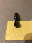
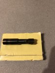
after I noticed, that my first selfmade tap has 11,56*0,5 mm, I made another one. With the support of the german forum "Zerspanungsbude" the second attempt looks better and cuts much better . With this lesson learned, I think special sized taps will be no problem in future.

IMG_0131.jpgIMG_0132.jpg

best regards

Edgar
 
Joined
Dec 15, 2014
Messages
6,782
Points
113
Hi, Good luck in the future making those taps I am sure it will come out well.

Rich:)
 

reloader45

Active member
Joined
Mar 17, 2019
Messages
172
Points
28
High Rich,

whenever I need a tap and can buy it for a reasonable price, I will buy it.

I only make special tools, if I am not able to order ist.
Not enough time to do all the things I want.


best regards

Edgar
 

reloader45

Active member
Joined
Mar 17, 2019
Messages
172
Points
28
Hello,

today I got my two 505 nm diodes. Both did not work until I realized, that they where case positiv. So I connected minus with plus and plus with minus. After that, I could see some bluish green. After this test, I pressed the diodes into a DTR module. What should I say, they are gone!!!
Is it possible, that the case positive diodes are more pressure sensitiv than the normal diodes?


best regards

Edgar
 
Joined
Sep 20, 2013
Messages
17,402
Points
113
Hello,

today I got my two 505 nm diodes. Both did not work until I realized, that they where case positiv. So I connected minus with plus and plus with minus. After that, I could see some bluish green. After this test, I pressed the diodes into a DTR module. What should I say, they are gone!!!
Is it possible, that the case positive diodes are more pressure sensitiv than the normal diodes?


best regards

Edgar
That has not been my experience with them. It is likely they were damaged when you tried them backwards.
 

reloader45

Active member
Joined
Mar 17, 2019
Messages
172
Points
28
Hello Paul,

I think you are right and I have to learn much more about laser diodes. The first diode runs even after the wrong wiring, but only for seconds.

The second Diode runs at my laboratory power source at 50 mA. Then I pressed it into the heat sink and it was dead.

I think, it was a problem of geometry and missing concentration!
I cut of the wrong pin very short and made a wrong wiring !
I will put this Diode into my hall of shame.
Two lessions learned:

1. never connect a new Diode without a look into the specification
2. Never cut a Diode pin before the system runs.

At the moment, I try to order some new Sharp GH05035A2G at Dongguan blue universe.
I am still waiting for a Driver for my 488 nm Diode.
The new 200 mA 405 nm boost Driver will only work for a second, than it shuts down.

best regards

Edgar
 
Joined
Sep 20, 2013
Messages
17,402
Points
113
How are you pressing diodes into modules? There are tools made especially for doing this. I use a large pair of channel locks with a piece of steel on the upper serrated edge to press all mine and I have never had an issue with doing it this way. You will need a press for each of the 3.8 mm, 5.6 mm and 9 mm sizes, but you can likely get by with just the 5.6 mm size at first. There are also presses to remove diodes from modules too.
 

reloader45

Active member
Joined
Mar 17, 2019
Messages
172
Points
28
Hello,

I use a little arbour press for this job. The press stamp has a 10 mm hole at the bottom.
I turned a 10mm brass rod, with a bore sufficient to take the diode pins without damage. That works fine for me. As I told, I did not kill the diode by pressing, I cut the wrong pin off!
Today, the 500 mA buck/boost driver from DTR arrived. They work fine with my new sharp 488 nm diode. Soldering is a tricky, because this driver is so little.
I run the driver at 280 mA input at 4,2V. That should be approx. 170 mA at the diode side. The laser output is 70 mW with a 3 element lense.
I am a little bit scrared to drive this diode harder.


best regards

Edgar
 
Joined
Sep 20, 2013
Messages
17,402
Points
113
Hello,

I use a little arbour press for this job. The press stamp has a 10 mm hole at the bottom.
I turned a 10mm brass rod, with a bore sufficient to take the diode pins without damage. That works fine for me. As I told, I did not kill the diode by pressing, I cut the wrong pin off!
Today, the 500 mA buck/boost driver from DTR arrived. They work fine with my new sharp 488 nm diode. Soldering is a tricky, because this driver is so little.
I run the driver at 280 mA input at 4,2V. That should be approx. 170 mA at the diode side. The laser output is 70 mW with a 3 element lense.
I am a little bit scrared to drive this diode harder.


best regards

Edgar

You can drive that diode at 275 mA. It is very happy at that current and outputs more than 100 mW. I have set many to this current and they run forever.....well not really. :LOL:
 
  • Like
Reactions: GSS

reloader45

Active member
Joined
Mar 17, 2019
Messages
172
Points
28
Hello,

how do you measure the current?. My experience shows, that with most drivers, the output current changes with the voltage of the laser diode.
So I can use a shunt resistor in the connection between driver and laser diode. But I hate to resolder this little contacts to get the big shunt out after measuring.
The other way would be a calculation when I run the driver with a laboratory power source. In this case I need to know the efficency of the driver.
I will not put my multimeter between the driver output and the diode. One bad connection and the driver is gone.
What is the best practice to measure the Laser current ?

I just see, that DTR powered this Diode over 600 mA. So 275 mA should be on the save side.
What is the recommendation for the 505 nm Diode? I ordered 4 cheap diodes direct from China, although the shipping costs are relativ high.

best regards

Edgar
 

DTR

0
Joined
Jun 24, 2010
Messages
5,684
Points
113
You will want to use a test load to set the current. A laser driver puts out a fixed current always as long as it is being powered as per the specs of the driver in the case of the LDSE500 is 2.9V-9V and the source can deliver all the current demand the driver is trying to draw from it which at most would be around 2A at the most.

You will not want to restrict current to the driver if that is what you meant either when you said you were feeding it only 275mA(if you did not mean that is what it was drawing) or via a resistor between the battery and driver as that can push the driver out of regulation.

If you have had a driver that does not maintain a fixed output current period then it is not a proper laser driver. So many drivers not suited for diodes being offered out there. The only reason for for it not to stay in regulation(supplying the diode a fixed current) is if the load or source voltages fall outside their min and max specs or the power source is not able to supply enough current for the demand of the driver.

An easy way to identify a improper driver is one that if you put on a teat load and vary the input voltage within its range or you add/remove voltage drop from the test load and the current does not stay fixed. Or if as the driver is powering the load it creeps up in current do due to thermal changes in the driver. If you see either of these toss it in the trash before you have to toss your diode there.

Yes you will always want a soldered and secure connection between the diode and driver after the current is set on the test load and the diode is connected without anything in series on the output of the driver like a Volt/Amp meter or DMM.

A short or any disconnect while running will usually blow the laser diode. This is one of the main reasons a test load is used and that we don't know the starting current when the driver is received.

Once the driver is connected to the diode via a soldered connection the pot should not be touched again as turning it blindly is not good and it is highly discouraged to turn the pot while the driver is powering the diode. Noise from the pot can cause transients that can damage the diode.

If it is desired to change the current desolder the diode from the driver and put the driver back on the test load to reset it.

For more info on how to build a teat load or to buy a nice premade one like the ones Survival lasers carries see this google search.

For some great info showing the minimum requirements according to a actual diode manufacturer see this.


I put up this video with a long description on setting a SXD and a good write up giving some basic info on laser drivers and how to use them. Needs some polishing but lot of good info laid out in there.


Here is a copy of what I had put in the description.

Super X-Drive(SXD-V3) Bucking Laser Driver by Lazeerer
ADJ(Adjustable current via potentiometer)
Current Setting Guide: Driver in - Range 1(1.6A-2.6A Adjustable)
Test Load: Lazeerer 5A X-LOAD -Jumper Setting 3(4V-5V drop with 1.5A-2A)
Power Source: Variable Power Supply.

*****PLEASE TAKE SPECIAL NOTE TO THE FOLLOWING WHICH IS REQUIRED********
• When setting the output current on a switching laser driver a test load that will simulate the voltage drop of the laser. If you are unsure how to make a test load or want a heavy duty more professional one see this search:https://www.google.com/search?rlz=1C1CHBD_enUS829US829&ei=xa72XLGXCMPktQXjlIeYCg&q=laser+test+load

• Never power a laser driver without a load. Either a test load when setting the current or once you have set the current the laser diode. Powering a laser driver with just a DMM connected is both pointless as it will not yield useful info and it could cause damage to the driver. You will not be able to set the output current like this and doing it to read the voltage will just give you the voltage of the power source the drier is connected to minus the regulator dropout which is usually 0.5V-1.5V. You can read the actual voltage of the power source on the input side of the driver if you want. This also has the risk of accidently shorting the output of the driver by accident which can damage the driver. If a driver gets damaged or the caps used on the output to smooth inrush to the diode can be left high charged since there was not load draining it continuously. This can spike and kill a diode if connected before this charge is fully discharged.

• To ensure no intermittent connection interrupt a direct connection between the diode pins and the pads output pads on the laser driver which is soldered and complete secure. Quick connects, hand twisted connections, ect.. should be avoided as any disconnect will charge up output caps and blow the diode when resumed. This is one clear sign that a driver was not designed with all the required extra safety features for a laser diode but is just a LED driver or basic DC-DC circuit. LED Drivers or DC-DC converters will be very abusive to laser diodes, have random event like overshoot during on switching and for sure will have no protection against undervotage shutdown voltage spikes which due to the sensitivity of the mirrors i the lasing cavity case serious desegregation. Most LED driver will run a laser diode for a short period, sellers expect that a returnee for a $10-$20 item(usually to a different county) will be more hassle than worth and the very expensive diode lost ends up being a more appealing item to blame for the failure.

• The current setting should never be changed other than when on a test load being set. Turning blind leaves with unknown current, adjusting a pot while powering a diode can cause noise and transients as well as shorts if say the mini screwdriver is not a non conductive blowing the diode. Also there is no safe way even if you could change the current like this as input current does not equal output current and putting DMM in series on output violates the secure soldered connection rule above preventing dissconnects.


SXD Super X-Drive working voltage range is 6V-12V and must be 1V over the voltage drop of the load.
Setting for power supply: 12V CV.
Important No CC limit that is the laser drivers job(meaning on variable power supply turn current knobs all the way to max.
Adjust the pot till the current out of the driver to desired.
Set this to 1.8A.
Caution if you are turning the pot up and the current stops rising but the pot has not hit the stop but can still turn clockwise any amount then either the supply voltage is less than 1V over the voltage of the test load or the power supply can not delivery the necessary current the laser driver it is trying to draw from it. Both of these scenarios are what is called "out of regulation" meaning the driver is no longer working in constant current. The actual set current could be considerably over what the reading gives and when the laser driver is installed on the output the driver can give that full set current to the diode and damage the laser if it is a current that is more than it can withstand.

Laser Drivers: Operating conditions As a semiconductor laser is inherently a current-driven device, a true current source is recommended for driving laser diodes. Laser diodes must not be driven by a voltage source. Similar to LEDs, the forward voltage depends on the junction temperature and differs from device to device. An ideal power supply for a laser diode has the following characteristics:

• Current source
• Transient suppression (also low noise)
• Independent clamping current limit
• Slow start / ramping the current signal during switch-on
• Output overvoltage protection • Input undervoltage detection
• Output short-circuit / interruption detection
• Shorting output during driver off status for ESD protection
• No undershooting of the output voltage at switch-off of the laser, so that a negative voltage over the laser diode cannot occur.
 
Last edited:

reloader45

Active member
Joined
Mar 17, 2019
Messages
172
Points
28
Hello,

this is a real long answer! Thank you for that big amount of professional information.
I have a test load, built from diodes and a shunt resistor.
I had a lot of trouble with cheap chines laser drivers. The 500 mA driver from your shop is an other categorie.
You are right, the driver drains 275 mA from the power supply. Missunderstanding happens when English is not your mother language.
Thinking about how to measure the current to the diode, I remembered, that I have a clamp current meter, that I can connect to the oscilloscope.
I will try, if this will give correct current measurement with a dummy load to the power device.


best regards

Edgar


Top