Welcome to Laser Pointer Forums - discuss green laser pointers, blue laser pointers, and all types of lasers

Buy Site Supporter Role (remove some ads) | LPF Donations

Links below open in new window

FrozenGate by Avery

505 nm laser diode

Hello,

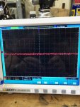
with the help of my oscilloscope, I increased the current off the 488 nm diode to 220 mA. That gave me an output of 102 mW. After going to to 250 , the driver input current switched from 400 mA to 550 mA with the same output of 250 mA. Because of this strange behaviour I decided to go back to 220 mA output of the driver.
After that, i tested the output of a cheap chinese driver with a M140 Diode at 1.500 mA. The oscilloscope showed an average current of 1500 mA with a lot of spikes between 1000 mA and 2000 mA.

I think this high spikes will kill the diode soon, so I will exchange the driver to a 1500 x-wossee driver.

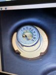
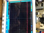
Attached you will find two photos of the diode without current and with approx. 170 mA current.
Neues Bild 1.JPGneues bild 2.JPG


best regards

Edgar


Just to remove any confusion, the scope trace shows a voltage of 170 mV, not 170 mA.
 
Hello,

yes, you are right, but this will be 170 mA driver oputput, measured with a current clamp.

best regards

Edgar
 
[QUOTE="reloader45]
Hello, this is a real long answer! Thank you for that big amount of professional information.
[/QUOTE]

No problem. Mostly copy/paste from something I had been working up and just a good timing.


[QUOTE="reloader45]
the driver input current switched from 400mA to 550mA with the same output of 250mA.
[/QUOTE]

That is not odd. They current draw will vary and the math to try to use it for useful calculations is not feasible. Any change in the source voltage or voltage being droped by the load will have a fixed output but varying current draw with switching drivers. The change in current draw could be if from going form the test load to the actual load, Voltage change with thermal change in the diode during the run. If battery powered the change in voltage during the battery cycle. Best to ignore current draw unless it does something really strange like shoot up showing some kind of short but other than that it is not that useful to keep an eye on it.

[QUOTE="reloader45]
After that, i tested the output of a cheap chinese driver with a M140 Diode at 1.500 mA. The oscilloscope showed an average current of 1500 mA with a lot of spikes between 1000 mA and 2000 mA.
[/QUOTE]

Thanks for posting. Did you already say which driver it is?
 
Hello,

this driver makes the spikes with my M 140 Diode:


Coming back to my 488nm Diode and the the 500 mW driver.

The driver was soldered to the Diode. Power input came fron my laboratory power supply. With the diode running, I increased the current to the diode slowly to 250 mA, measured with the current clamp. At this condition, the driver drained 400 mA. Than I switched the power off. After switching the power on, the driver drained more than 500 mA from the laboratory power supply. That is a jump of 20% !
At 220 mA to the diode, the power input is stabil. I thought, this was a laser diode effekt, although I did nit measure the voltage drope of the diode. So I run the diode at 220 mA to be on the safe side.
I think, i will built some LM 317 linear drivers for test purpose and see how they look at the oscilloscope.

The noise, that you can see at my oscilloscope pictures is from the current clamp. The clamp is made for currents up to 60 A. So it is not ideal for such low loads.

best regards

Edgar
 
You really can't effectively limit the current to the driver with a power supply as it will draw the current necessary to supply the diode based on the voltage across the driver's input. If you try to limit it the driver won't be able to regulate properly. Most power supplies have the current displayed as well as the voltage, so it isn't necessary to measure this twice. I keep my leads short coming from a supply so the voltage won't be dropped as much across the leads. This gives me a more accurate readout of the voltage going to the driver.
 
Hello,

The power supply was set on constant voltage. I did not limit the current!

Best regards

Edgar
 
Hello,

today I set the current for my 488 nm diode to 280 mA. That beam looks nice, but I think, it changed a little more to green.
I also could solve the problem with the strange behaviour or the driver. The current setting of of my power supply was too low.
So I run into the current regulation of the power supply. After I increased the current limit, the driver reacts normal.

best regards

Edgar
 
These diodes take 280 mA fine. They aren't prone to a wavelength shift by a current increase, especially one so modest. I have measured the wavelengths on many of these diodes at currents ranging from threshold to 350 mA. They tend to shift more with an increase in temperature, so as long as the diode is well heatsunk it won't shift much.
 
At this wavelength even the smallest change can be visible as the diode warms up.
 
Hello,

today my cheap 505nm sharp diodes from Dongguan blue universe arrived. I will press one diode into a 12 mm DTR heat sink.
I will use a 500 mA buck boost Driver and a nice convoy S2 host.
How high can I drive this Diode without risk of sudden burn out?

200 mA or less?


best regards


Edgar
 
Hello,
today my cheap 505nm sharp diodes from Dongguan blue universe arrived. I will press one diode into a 12 mm DTR heat sink.
I will use a 500 mA buck boost Driver and a nice convoy S2 host.
How high can I drive this Diode without risk of sudden burn out?
200 mA or less?
best regards
Edgar

To make sure you get the right info can you give the number that is on the top of the can if not on the top of the can there should be one on the side of the can like these examples. The one on the side can be hard to see as at some angles. Almost hologram like.

 
Hello,


I had to learn, that I had no 500 mA driver left. So I set a LM 317 to 60 mA. The diode was very dim, but gets much better at 100mA.
It was hard to see, that the LM317 did not regulate with this diode at 8,4V. The voltage drop of the diode is too high.
Tomorrow I will desolder the 500 mA driver from my 405nm diode.


best regards

Edgar
 
Ok so it is a SB14 which should be case negative. Just wanted to make sure. Have not see the bin code 7F6. Started a sheet to try and map out what all the codes are and see if we can work out a pattern.
Anyone wants edit access to help fill it in pm me an email address.

This is probably similar to the ones I tested here which I was setting 200mA-250mA and did not have any problems.

 
Hello,

so I will drive the diode harder. I bought 4 of them, one can be used for a test run.


best regards

Edgar


Back
Top