
Welcome to Laser Pointer Forums - discuss green laser pointers, blue laser pointers, and all types of lasers
How to Register on LPF | LPF Donations

Navigation
Install the app
How to install the app on iOS
Follow along with the video below to see how to install our site as a web app on your home screen.
Note: This feature may not be available in some browsers.
More options
You are using an out of date browser. It may not display this or other websites correctly.
You should upgrade or use an alternative browser.
You should upgrade or use an alternative browser.
Unknown Red diode
- Thread starter jtroutt19
- Start date
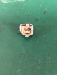


After reading a bit I have learned this is an open can diode. If I have understood correctly I should be able to use and module that accepts a 3.8mm diode. Looking on DTR's shop I was doing to get a 12mm module with a 3 element glass lens.
What driver should I get to power this thing?
What driver should I get to power this thing?
Immo1282
0
- Joined
- Sep 4, 2018
- Messages
- 562
- Points
- 63
Not sure how you'd remove that open-can diode from that housing it's mounted in to then press it into a module, but yeah - these aren't that uncommon. I've got a build done by Trinh Hong Phuoc that has an open-can Mitsubishi ML501P73 open-can 638nm diode pushing 1W.
It might not be 3.8mm - that dimension is across the body of the "can", obviously in this case there isn't one - but if you measure the approximate aperture of that exterior housing you may have luck there.
Unfortunately with open-can diodes, they're extremely easy to mess up with dust etc - so be extremely careful with it!
- Joined
- Sep 16, 2007
- Messages
- 3,667
- Points
- 113
Not sure how you'd remove that open-can diode from that housing it's mounted in to then press it into a module, but yeah - these aren't that uncommon.
A sharp, precise file should cut through the heat sink around the diode easily. The material is brittle and should be easy to snap off (carefully) once it's thin enough.
Also, are you sure this is a 3.8 mm diode? There are also open can 9 mm and 5.6 mm TO-package diodes.
The diode will slip right out of the current housing. Other than being out for literally 2 seconds it hasnt been removed. The measurement of the aperture is ~4.75mm. The diode does not have any kind of identifier on it unfortunately, not sure how I can identify it.
Immo1282
0
- Joined
- Sep 4, 2018
- Messages
- 562
- Points
- 63
it's definitely not a 3.8mm diode if it's that large! - you'll want a module with a 5.6mm hole for it.
RA, wouldn't a file cause havoc introducing all sorts of metal particles onto the actual die?
A sharp, precise file should cut through the heat sink around the diode easily.
RA, wouldn't a file cause havoc introducing all sorts of metal particles onto the actual die?
it's definitely not a 3.8mm diode if it's that large! - you'll want a module with a 5.6mm hole for it.
RA, wouldn't a file cause havoc introducing all sorts of metal particles onto the actual die?
That’s what I was thinking after measuring it. How do I find out voltage and current to drive it at
Immo1282
0
- Joined
- Sep 4, 2018
- Messages
- 562
- Points
- 63
I'd start low and ramp up the current slowly. Laser Diodes require current regulation - as their resistance reduces when they get hotter, allowing for thermal runaway & damage if a voltage-regulated supply is used. So you should either use a decent constant-current bench supply, or a dedicated Linear or Buck laser driver designed for red diodes. I'd expect a forward voltage of between 2.5-3V give or take, but it must be current limited, and start with only a few milliamps.How do I find out voltage and current to drive it at
- Joined
- Dec 15, 2014
- Messages
- 6,773
- Points
- 113
hi,
I use a small wire cutting pliers to make relief cuts around the case, then just break off the sections. This is the same way I do for a BRD-209/405nm sleds. Then after you figure out the size diode press it into to the selected 12mm module put it in a larger heat sink and hook it up to your PSU. Find out the size by measuring the diameter with a pair of caliper set to MM. Looking at the back of the diode you should see three detents one at 12'0clock .3'0clock ,6'0clock usually POS 12 o'clock /case pin 3 0'clock/NEG 6 0'clock.
And yes its an open can diode
Rich")
I use a small wire cutting pliers to make relief cuts around the case, then just break off the sections. This is the same way I do for a BRD-209/405nm sleds. Then after you figure out the size diode press it into to the selected 12mm module put it in a larger heat sink and hook it up to your PSU. Find out the size by measuring the diameter with a pair of caliper set to MM. Looking at the back of the diode you should see three detents one at 12'0clock .3'0clock ,6'0clock usually POS 12 o'clock /case pin 3 0'clock/NEG 6 0'clock.
And yes its an open can diode
Rich
diachi
0
- Joined
- Feb 22, 2008
- Messages
- 9,700
- Points
- 113
Looks like a short open can, so probably good for 250-300mA with a decent heatsink. Can buy those new for <$10.
- Joined
- Sep 16, 2007
- Messages
- 3,667
- Points
- 113
RA, wouldn't a file cause havoc introducing all sorts of metal particles onto the actual die?
Yes, if you're not careful. In the past when I was extracting most of my diodes, some materials around some diodes were too tough or awkwardly shaped for clippers. A file was the only option. As long as you hold the diode with the emitter facing downward and use good filing technique, it shouldn't be a problem. It was never a problem for me. $0.02
It won’t be a problem at all given that this diode can be pulled out with ease. Looking at DTR’s shop a module and driver are gonna cost me about $60 bucks......
Has there been a user designed driver that the board files and BOM are available for those that want to order boards and assemble the driver themselves?
Has there been a user designed driver that the board files and BOM are available for those that want to order boards and assemble the driver themselves?
diachi
0
- Joined
- Feb 22, 2008
- Messages
- 9,700
- Points
- 113
It won’t be a problem at all given that this diode can be pulled out with ease. Looking at DTR’s shop a module and driver are gonna cost me about $60 bucks......
Has there been a user designed driver that the board files and BOM are available for those that want to order boards and assemble the driver themselves?
An LM317 in constant current mode does the job. Schematics for that in the datasheet for the LM317. Can breadboard it throw together a PCB quickly if you really want to go to the effort. Can be built with two components, 4-5 if you want to do it properly.
Immo1282
0
- Joined
- Sep 4, 2018
- Messages
- 562
- Points
- 63
Yep - the cheapest way to put together a driver is definitely an LM317 - look online (or search the forum, top right for the search bar!) for schematics.
The higher the difference between input and output the more the LM317 IC will dissipate as heat, so I suggest to power it off a 5V input. An LM317 cannot boost the output voltage to cause a constant current to flow - only drop it, so it will likely be badly current limited if you try and use a single Li-Ion battery or something.
The higher the difference between input and output the more the LM317 IC will dissipate as heat, so I suggest to power it off a 5V input. An LM317 cannot boost the output voltage to cause a constant current to flow - only drop it, so it will likely be badly current limited if you try and use a single Li-Ion battery or something.
- Joined
- Dec 15, 2014
- Messages
- 6,773
- Points
- 113
Hi, Or if you want you can see the micro flex V5 driver for 25.00 , leave it in the 1st range and set it to your desired Amp. If you need a host I have one to go great with that diode . Prewired and holds 1X 18650 or 2X18350 30.00 + 4.00 ship 1st class
Rich


Rich
diachi
0
- Joined
- Feb 22, 2008
- Messages
- 9,700
- Points
- 113
Yep - the cheapest way to put together a driver is definitely an LM317 - look online (or search the forum, top right for the search bar!) for schematics.
The higher the difference between input and output the more the LM317 IC will dissipate as heat, so I suggest to power it off a 5V input. An LM317 cannot boost the output voltage to cause a constant current to flow - only drop it, so it will likely be badly current limited if you try and use a single Li-Ion battery or something.
Might need a hair more than 5V depending on the LD and current. 5V input in constant current mode gives you a max output of 2.5V.