

- Joined
- Sep 16, 2007
- Messages
- 3,667
- Points
- 113
I've been planning this project for a long time but finally had some time to get around to setting it up today.
The idea: Make a tiny, optical correction assembly to improve the beam quality from high power multimode diodes while minimizing losses and cost.
The materials:
Phase 1: Proof of concept
There are a few hurdles to overcome with this project.
The first is that I don't own my own metal-working tools so I am limited to scraps from disassembled modules and basic tools one might find in a relatively well-equipped garage.
After rummaging through my spare parts box, I found a few pieces I could put together with a little modification to get an adjustable otpics assembly.
The second hurdle is finding the right optics. I went to Edmund Optics and selected a couple lenses that would provide decent correction for the average divergence specifications given by the datasheet for the diode. This required some algebra, a little trigonometry, and less physics. The basic idea is to select focal lengths that provide the same ratio as the divergence angles of the diode's emission axes.
Once I had the materials in hand, it was just a matter of finding the time and doing the work.
The design is crude but effective.
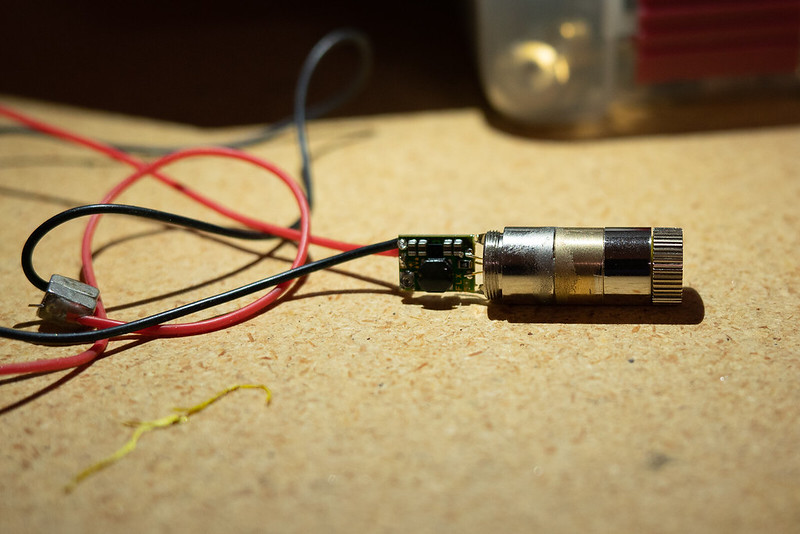
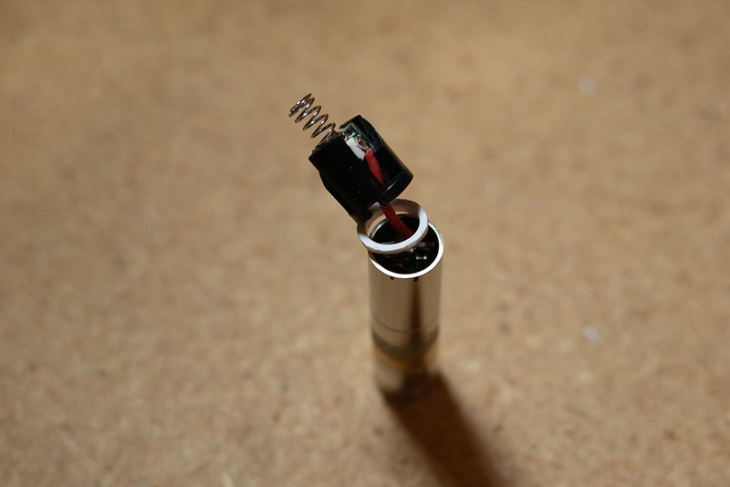
The diode is seated, for now, in a threaded mount so that it can be removed or rotated if necessary.
The first lens is mounted on a threaded ring in a brass tube that threads onto the diode mount.
The second lens is also mounted on a threaded ring in a brass tube that is connected to the first lens assembly by another threaded ring.
That's it.
This design allows me to adjust the z-position of each lens relative to the diode by threading in or out the ring that the lens is to be mounted on.
The lens rotation and x-y position can be adjusted freely. This part is tedious and difficult.
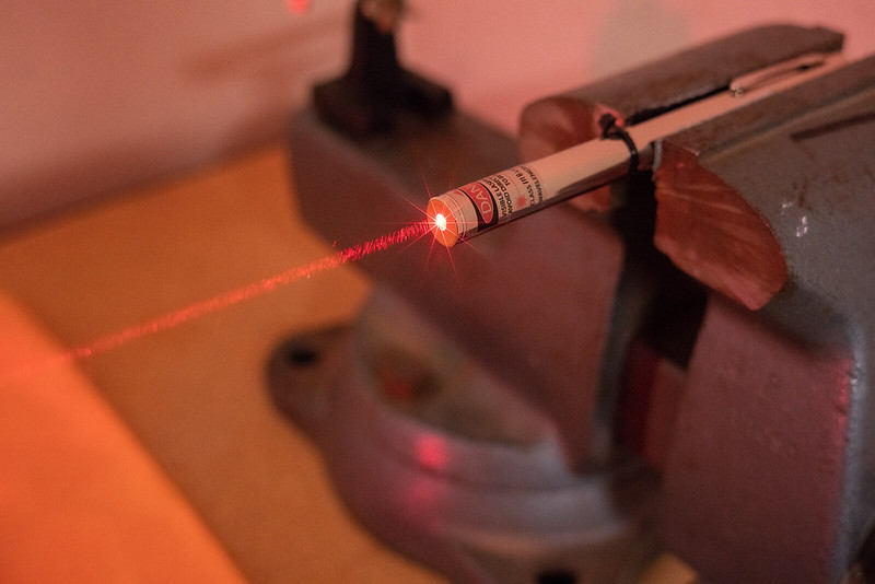
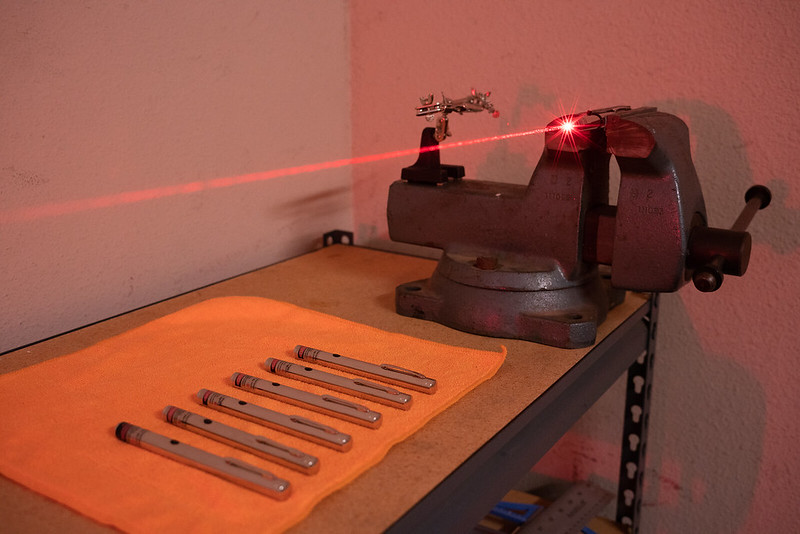
To ensure a good alignment, I first mounted the diode and powered it up above lasing threshold (around 40mW) then redirected the output to an adjacent wall with a first-surface mirror.
The z-position of each lens was set first by crudely aligning the lenses one at a time to achieve the smallest divergence angle at the other side of the garage.
I marked on the wall what I could approximate was the center of the beam profile with a marker. For each lens, I would target this mark for the center of the beam when making adjustments to the x-y position.
When positioned, I applied a small drop of UV-cure liquid plastic to set the optic in place. This required a lot of patience and a steady hand but the process is simple.
Results:
I achieved about 1.5mRad divergence on the fast-diverging axis of the diode.
Unfortunately, while setting the lenses with epoxy for a more permanent hold, I had to disassemble the optic mounts. When I put it back together the second lens had shifted somehow and the divergence is around 2.5mRad on one axis now. This will be corrected for the second iteration of this assembly when it is ready to go into a host.
Addendum 5/28: After adjustment I'm getting approximately 1mRad measured at 20 feet for the fast-diverging axis.
The module as it is now, is about 35mm long which can be shortened by a couple millimeters by clipping the diode pins. It may be possible to achieve a total module length of about 40mm with the switch board included. I will try my best to keep the size small so that it can fit nicely into a pen.
After alignment, I increased the power a bit to check losses to the optics.
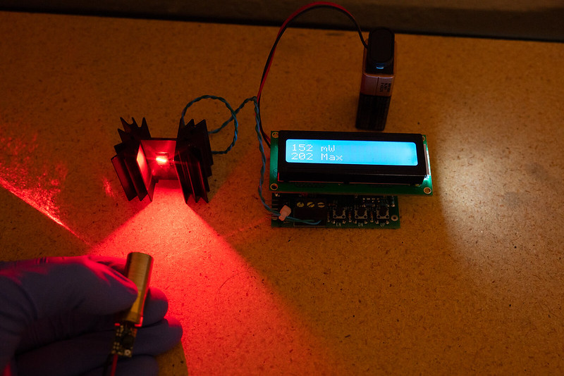
The raw output from the diode (no optics) was 200mW. After both correction lenses, I was getting 150mW. This comes out to about 25% loss which I think is quite good when considering that these lenses ended up being a bit too small to collect the entire beam (the divergence of the fast axis is a bit higher than specified on the diode's datasheet) and that the apertures at the first lens cuts off some of the output as well.
400mW is easy to obtain with this setup (and it's bright!).
What I learned:
One issue I have is that the mounting method for this diode does not provide enough heat transfer to the module. A press-fit would be much better. In future renditions, this will be possible if I can get someone to machine the parts I need. Because heat transfer is poor, power drops rapidly at high current input.
Choosing lenses with shorter focal lengths should allow a more compact design but it will be difficult to find such lenses with a large enough clear aperture that will minimize losses.
There is still some crap spilling over the main output modes after correction. This will be difficult to eliminate without spatial filtering (another project) but can be cut down a little with masking using a narrow exit aperture. I have to experiment with this more.
Addendum 5/28:The ratio of the focal lengths for this diode is not exactly right so I still get more of a line-shaped beam. I think that for the finished set-up, I'll try leaving the first lens slightly de-focused to match the divergence of both axes for more of a square beam.
Additionally, I measured the output power at 2 inches from the LPM sensor and at 24 inches. I estimate that about 30% of the total power is contained within the lobes. I'm curious to know how this scales when power is increased. I'll do more testing for that later.
The photos:
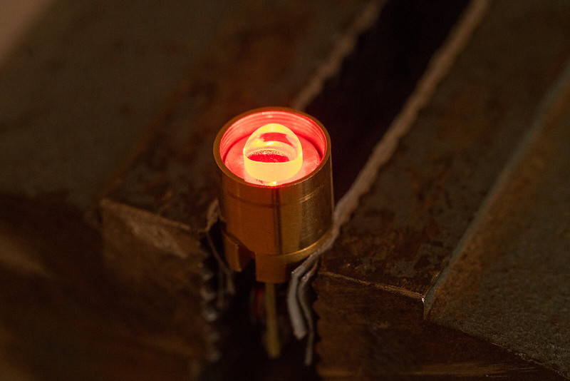
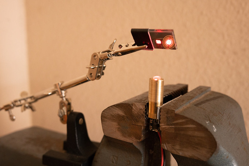
Positioning the first lens
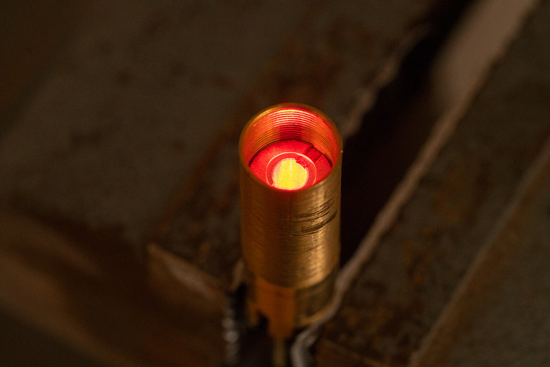
Positioning the second lens
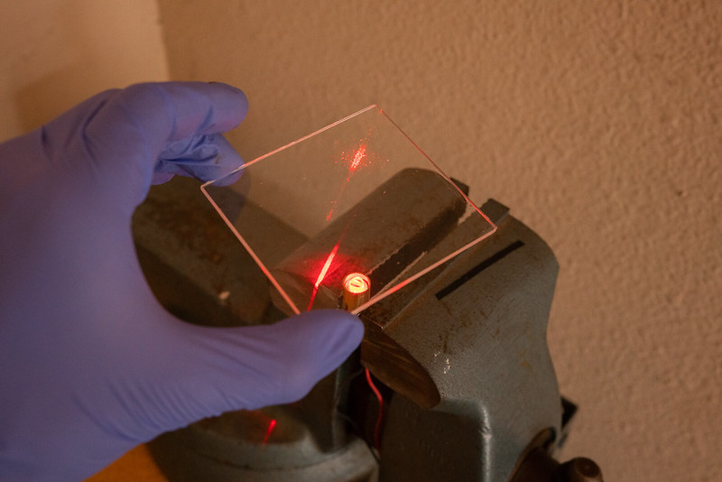
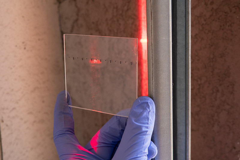
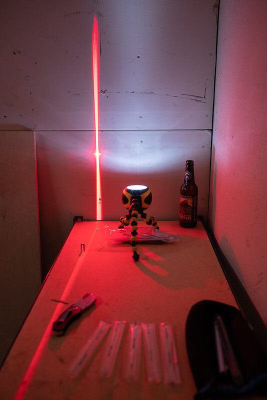
I can check for the presence of a positive focal point and observe the general profile by passing the beam through clear acrylic
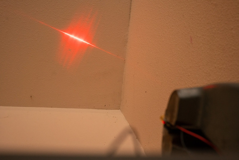
Before optical correction
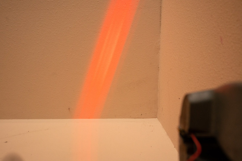
After the first lens is roughly aligned
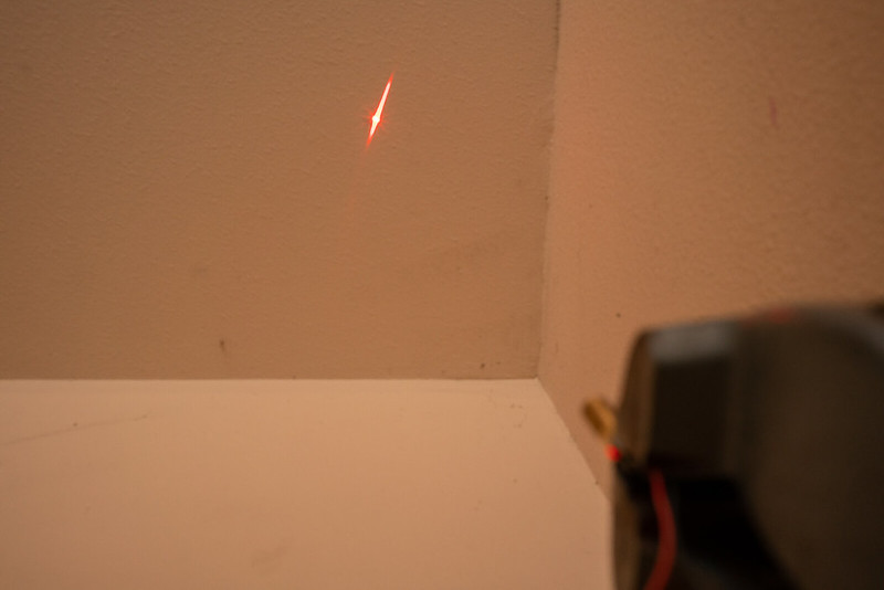
After the second lens is roughly aligned you can see that the main portion of the output is concentrated and there is some spill from the uncollimated modes at low intensity on either side of the beam
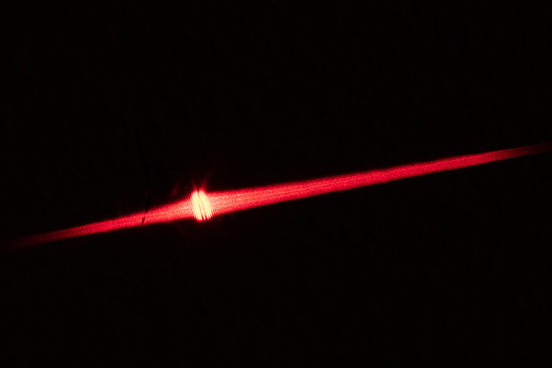
A close-up of the profile before final alignment (slightly imperfect collimation)
A first-surface mirror can be used to position the beam in a more convenient location so the lenses can be installed vertically with the help of gravity to keep them in place
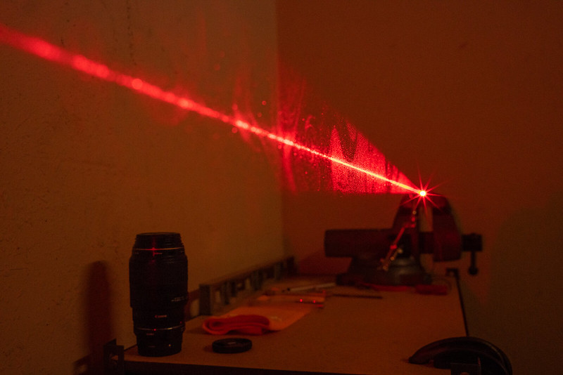
Divergence at 20 feet (markings for centimeters and 5mm intervals
A power test showing raw output power (bottom measurement) and the power after optics are installed (top measurement)
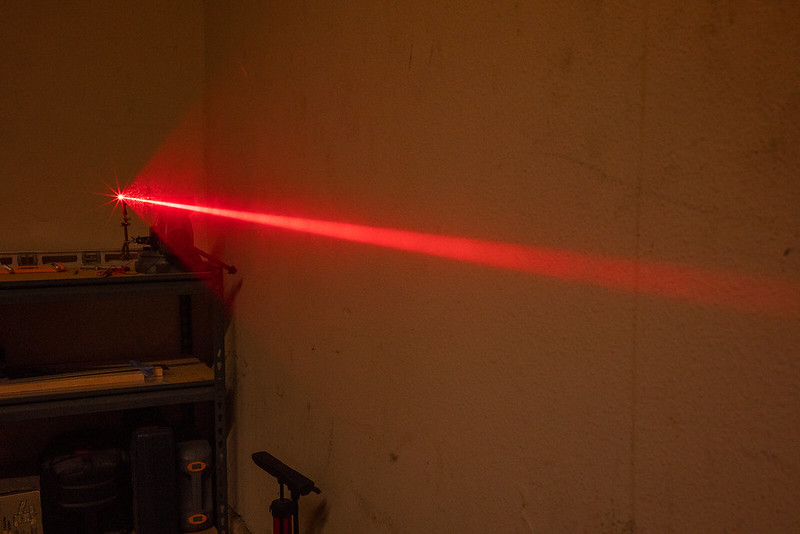
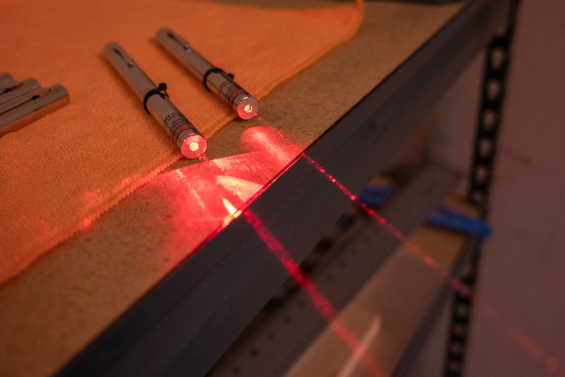
Beamshots. The perspective exaggerates the beam size but divergence is lower than with 3-element glass lens
Phase 2: Fine-tuning and assembly into host
Because of the heat transfer issues I was having, I took the module apart and set the diode in a regular ol' nickel plated brass Aixiz module.
This improves heat-sinking but has some drawbacks.
First, this makes it a little more difficult to install the first cylindrical lens within the narrow space of the Aixiz module aperture.
Second, I would need spacer tubes threaded for 9mm lens holders to allow me to make the module long enough for correct placement of the second lens. To get these parts, it took a few hours of manual sawing, filing, sanding, fitting, re-filing, re-sanding, re-fitting, then more testing...
There is also a third issue that I haven't addressed previously but I have a solution for already. The module length extended past the length of the leadlight host. I couldn't leave it that way as it would look unfinished and a little ugly.
Optical Assembly:
Lens 1: I took an old 9mm threaded lens ring from a 3-element lens , then filed and sanded the surfaces flat and smooth, and removed burrs to prevent scratching the lens.
Because the lens must be positioned close to the diode (4.55mm), I couldn't easily mount the lens on top of the lens mount. Fortunately, the lenses I purchased are the same diameter as the lenses that go into the 3-element lenses. This allowed me to drop lens 1 into the mount, adjust the height and then rotate it to correct the fast-axis properly.
While this simplifies the setup process, the centering is not perfect and is unfortunately not adjustable this way. It is close enough for me, for this prototype.
Lens 2: To mount the second lens, I sawed off the diode mounting socket from a couple of Aixiz modules, filed and sanded the surfaces flat and smooth, and removed the burrs. This produced two 12mm M9x0.5 threaded tubes Next, I took another 3-element lens holder and cut this one in half.
Of these two pieces, one would be used to join the module pieces together and the last one would be used to mount the second lens.
I'll save the explanation and update this section with a drawing.
After all the parts were verified to fit together, I started assembling the optics.
Part of the complication introduced by this design is that the first lens mount also serves to join pieces of the module together. This means that when the second module spacer tube is threaded on, it introduces a little rotation to the lens mount. To get around this, I used teflon tape to tighten the threads around the section of the lens mount that would be installed inside the module containing the diode. This minimizes rotation of this section while allowing the spacer tube to be threaded on freely.
I also installed the lens mount a quarter-turn short of where it needed to be so that when the spacer tube is tightened down, it makes that last quarter turn of the lens mount and gets it into the right place. This took a lot of trial and error to get just right.
Once the first lens was in position, I bonded it in place by carefully applying a tiny amount of bondic to secure the position instantly and then 2-part epoxy for a more permanent hold.
The second lens was easy. Because it protrudes from the module, access is good so its position can be adjusted easily in all directions.
The setup was essentially the same as in Phase 1.
With the optical assembly completed, that just left wiring up the driver for installation in a pen host, assembling all the little bits for that, then fitting it into the host.
Final Assembly in the Leadlight host:
To make the module as short as possible, I cut off a few millimeters from the back portion of the module (the threaded tube that threads onto the back of the diode socket). However, because this leaves an open tube, mounting the switch board assembly is a little harder with less surface area to bond everything with epoxy.
To mediate, I found a piece of plastic in my spare parts bin that had a "lip" that fit right into the back of the module. I trimmed it to 12mm diameter and epoxied it in place. This would provide more surface area to bond with the module back and provide a more secure bond with the switch board assembly (plastic-plastic bonds more strongly than brass-plastic especially between two flat surfaces). This is shown in one of the photos.
One thing about this build that turned out quite nice is the amount of mass contained within this pen. Because I am using these cut up Aixiz modules, there is a lot more metal available for heat-sinking than with the previous setup using the wider brass threaded tube. The laser feels heavy and I think all that metal helps move the heat away effectively.
As I mentioned several paragraphs ago, one issue with this module is that it's too long for the host. It protrudes almost exactly 10mm.
The solution for this is simple: hack off a section of another Leadlight host and stick it on top.
That's what I did. Of course, I took care to make sure the sawed surface was flat and flush. I did this for the 532nm aspheric pen I put together a few months ago (I still haven't showed that one off yet).
There's not much more to say about it. I crammed everything together then buffed out the smudges and put a sticker on it.
Voilà!
Photos, then final details follow:
The module. I have the knurled focus ring on there just to protect lens 2 which would otherwise be exposed.
The switch board assembly and the plastic spacer to get a stronger bond to the module
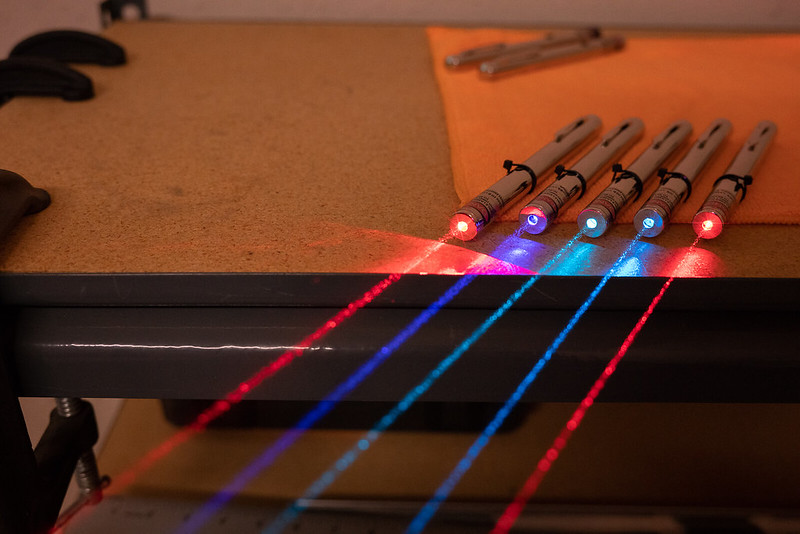
A comparison with 150mW 638nm single-mode (right)
The newest addition to the collection
In case you were wondering about what some of these other lasers are:
638 MM, 450 SM, 495 SM, 488 SM, 638 SM
Here's a view of the beam profile.
The "wings" are quite pronounced but there's no easy way to get rid of them in this setup. I think it gives this laser a unique character.
Summary and final thoughts:
Divergence (corrected fast-axis): 0.9mRad
Divergence (G- lens fast axis):
Power output: 400mW peak
Loss to optics: 25%
This build was challenging but a lot of fun.
I think that the optical correction done here is quite effective, though, depending on what you expect and want from a diode like this, the results could be disappointing.
While the corrective optics do substantially improve the divergence of the output from these notoriously bad red multimode diodes, a lot of the total power is lost in the lobes that extend beyond the "main beam." Some might call it ugly and I can understand that. However, it's about what I expected and now that I have this thing all put together, it really doesn't bother me.
"It's a different type of laser," my girlfriend says.
It's true. We have a bunch of cool stuff available these days and it seems there is a lot of discussion surrounding correcting the "artifacts" or improving the beam quality from the less-than-perfect diode lasers. But I think if you can appreciate the weirdness of the engineering and physics that go into making these, by appreciating the unique aesthetic of each type of laser, you'll find that there is another aspect to our laser collections that is underrated: the variety of beam types.
The idea: Make a tiny, optical correction assembly to improve the beam quality from high power multimode diodes while minimizing losses and cost.
The materials:
- HL63193MG 638nm Diode
- 6mm cylindrical lens (AR coated for 633nm)
- 25mm cylindrical lens (AR coated for 633nm)
- Flexdrive V5
- Spare parts
Phase 1: Proof of concept
There are a few hurdles to overcome with this project.
The first is that I don't own my own metal-working tools so I am limited to scraps from disassembled modules and basic tools one might find in a relatively well-equipped garage.
After rummaging through my spare parts box, I found a few pieces I could put together with a little modification to get an adjustable otpics assembly.
The second hurdle is finding the right optics. I went to Edmund Optics and selected a couple lenses that would provide decent correction for the average divergence specifications given by the datasheet for the diode. This required some algebra, a little trigonometry, and less physics. The basic idea is to select focal lengths that provide the same ratio as the divergence angles of the diode's emission axes.
Once I had the materials in hand, it was just a matter of finding the time and doing the work.
The design is crude but effective.
The diode is seated, for now, in a threaded mount so that it can be removed or rotated if necessary.
The first lens is mounted on a threaded ring in a brass tube that threads onto the diode mount.
The second lens is also mounted on a threaded ring in a brass tube that is connected to the first lens assembly by another threaded ring.
That's it.
This design allows me to adjust the z-position of each lens relative to the diode by threading in or out the ring that the lens is to be mounted on.
The lens rotation and x-y position can be adjusted freely. This part is tedious and difficult.
To ensure a good alignment, I first mounted the diode and powered it up above lasing threshold (around 40mW) then redirected the output to an adjacent wall with a first-surface mirror.
The z-position of each lens was set first by crudely aligning the lenses one at a time to achieve the smallest divergence angle at the other side of the garage.
I marked on the wall what I could approximate was the center of the beam profile with a marker. For each lens, I would target this mark for the center of the beam when making adjustments to the x-y position.
When positioned, I applied a small drop of UV-cure liquid plastic to set the optic in place. This required a lot of patience and a steady hand but the process is simple.
Results:
I achieved about 1.5mRad divergence on the fast-diverging axis of the diode.
Unfortunately, while setting the lenses with epoxy for a more permanent hold, I had to disassemble the optic mounts. When I put it back together the second lens had shifted somehow and the divergence is around 2.5mRad on one axis now. This will be corrected for the second iteration of this assembly when it is ready to go into a host.
Addendum 5/28: After adjustment I'm getting approximately 1mRad measured at 20 feet for the fast-diverging axis.
The module as it is now, is about 35mm long which can be shortened by a couple millimeters by clipping the diode pins. It may be possible to achieve a total module length of about 40mm with the switch board included. I will try my best to keep the size small so that it can fit nicely into a pen.
After alignment, I increased the power a bit to check losses to the optics.
The raw output from the diode (no optics) was 200mW. After both correction lenses, I was getting 150mW. This comes out to about 25% loss which I think is quite good when considering that these lenses ended up being a bit too small to collect the entire beam (the divergence of the fast axis is a bit higher than specified on the diode's datasheet) and that the apertures at the first lens cuts off some of the output as well.
400mW is easy to obtain with this setup (and it's bright!).
What I learned:
One issue I have is that the mounting method for this diode does not provide enough heat transfer to the module. A press-fit would be much better. In future renditions, this will be possible if I can get someone to machine the parts I need. Because heat transfer is poor, power drops rapidly at high current input.
Choosing lenses with shorter focal lengths should allow a more compact design but it will be difficult to find such lenses with a large enough clear aperture that will minimize losses.
There is still some crap spilling over the main output modes after correction. This will be difficult to eliminate without spatial filtering (another project) but can be cut down a little with masking using a narrow exit aperture. I have to experiment with this more.
Addendum 5/28:The ratio of the focal lengths for this diode is not exactly right so I still get more of a line-shaped beam. I think that for the finished set-up, I'll try leaving the first lens slightly de-focused to match the divergence of both axes for more of a square beam.
Additionally, I measured the output power at 2 inches from the LPM sensor and at 24 inches. I estimate that about 30% of the total power is contained within the lobes. I'm curious to know how this scales when power is increased. I'll do more testing for that later.
The photos:
Positioning the first lens
Positioning the second lens
I can check for the presence of a positive focal point and observe the general profile by passing the beam through clear acrylic
Before optical correction
After the first lens is roughly aligned
After the second lens is roughly aligned you can see that the main portion of the output is concentrated and there is some spill from the uncollimated modes at low intensity on either side of the beam
A close-up of the profile before final alignment (slightly imperfect collimation)
A first-surface mirror can be used to position the beam in a more convenient location so the lenses can be installed vertically with the help of gravity to keep them in place
Divergence at 20 feet (markings for centimeters and 5mm intervals
A power test showing raw output power (bottom measurement) and the power after optics are installed (top measurement)
Beamshots. The perspective exaggerates the beam size but divergence is lower than with 3-element glass lens
Phase 2: Fine-tuning and assembly into host
Because of the heat transfer issues I was having, I took the module apart and set the diode in a regular ol' nickel plated brass Aixiz module.
This improves heat-sinking but has some drawbacks.
First, this makes it a little more difficult to install the first cylindrical lens within the narrow space of the Aixiz module aperture.
Second, I would need spacer tubes threaded for 9mm lens holders to allow me to make the module long enough for correct placement of the second lens. To get these parts, it took a few hours of manual sawing, filing, sanding, fitting, re-filing, re-sanding, re-fitting, then more testing...
There is also a third issue that I haven't addressed previously but I have a solution for already. The module length extended past the length of the leadlight host. I couldn't leave it that way as it would look unfinished and a little ugly.
Optical Assembly:
Lens 1: I took an old 9mm threaded lens ring from a 3-element lens , then filed and sanded the surfaces flat and smooth, and removed burrs to prevent scratching the lens.
Because the lens must be positioned close to the diode (4.55mm), I couldn't easily mount the lens on top of the lens mount. Fortunately, the lenses I purchased are the same diameter as the lenses that go into the 3-element lenses. This allowed me to drop lens 1 into the mount, adjust the height and then rotate it to correct the fast-axis properly.
While this simplifies the setup process, the centering is not perfect and is unfortunately not adjustable this way. It is close enough for me, for this prototype.
Lens 2: To mount the second lens, I sawed off the diode mounting socket from a couple of Aixiz modules, filed and sanded the surfaces flat and smooth, and removed the burrs. This produced two 12mm M9x0.5 threaded tubes Next, I took another 3-element lens holder and cut this one in half.
Of these two pieces, one would be used to join the module pieces together and the last one would be used to mount the second lens.
I'll save the explanation and update this section with a drawing.
After all the parts were verified to fit together, I started assembling the optics.
Part of the complication introduced by this design is that the first lens mount also serves to join pieces of the module together. This means that when the second module spacer tube is threaded on, it introduces a little rotation to the lens mount. To get around this, I used teflon tape to tighten the threads around the section of the lens mount that would be installed inside the module containing the diode. This minimizes rotation of this section while allowing the spacer tube to be threaded on freely.
I also installed the lens mount a quarter-turn short of where it needed to be so that when the spacer tube is tightened down, it makes that last quarter turn of the lens mount and gets it into the right place. This took a lot of trial and error to get just right.
Once the first lens was in position, I bonded it in place by carefully applying a tiny amount of bondic to secure the position instantly and then 2-part epoxy for a more permanent hold.
The second lens was easy. Because it protrudes from the module, access is good so its position can be adjusted easily in all directions.
The setup was essentially the same as in Phase 1.
With the optical assembly completed, that just left wiring up the driver for installation in a pen host, assembling all the little bits for that, then fitting it into the host.
Final Assembly in the Leadlight host:
To make the module as short as possible, I cut off a few millimeters from the back portion of the module (the threaded tube that threads onto the back of the diode socket). However, because this leaves an open tube, mounting the switch board assembly is a little harder with less surface area to bond everything with epoxy.
To mediate, I found a piece of plastic in my spare parts bin that had a "lip" that fit right into the back of the module. I trimmed it to 12mm diameter and epoxied it in place. This would provide more surface area to bond with the module back and provide a more secure bond with the switch board assembly (plastic-plastic bonds more strongly than brass-plastic especially between two flat surfaces). This is shown in one of the photos.
One thing about this build that turned out quite nice is the amount of mass contained within this pen. Because I am using these cut up Aixiz modules, there is a lot more metal available for heat-sinking than with the previous setup using the wider brass threaded tube. The laser feels heavy and I think all that metal helps move the heat away effectively.
As I mentioned several paragraphs ago, one issue with this module is that it's too long for the host. It protrudes almost exactly 10mm.
The solution for this is simple: hack off a section of another Leadlight host and stick it on top.
That's what I did. Of course, I took care to make sure the sawed surface was flat and flush. I did this for the 532nm aspheric pen I put together a few months ago (I still haven't showed that one off yet).
There's not much more to say about it. I crammed everything together then buffed out the smudges and put a sticker on it.
Voilà!
Photos, then final details follow:
The module. I have the knurled focus ring on there just to protect lens 2 which would otherwise be exposed.
The switch board assembly and the plastic spacer to get a stronger bond to the module
A comparison with 150mW 638nm single-mode (right)
The newest addition to the collection
In case you were wondering about what some of these other lasers are:
638 MM, 450 SM, 495 SM, 488 SM, 638 SM
Here's a view of the beam profile.
The "wings" are quite pronounced but there's no easy way to get rid of them in this setup. I think it gives this laser a unique character.
Summary and final thoughts:
Divergence (corrected fast-axis): 0.9mRad
Divergence (G- lens fast axis):
Power output: 400mW peak
Loss to optics: 25%
This build was challenging but a lot of fun.
I think that the optical correction done here is quite effective, though, depending on what you expect and want from a diode like this, the results could be disappointing.
While the corrective optics do substantially improve the divergence of the output from these notoriously bad red multimode diodes, a lot of the total power is lost in the lobes that extend beyond the "main beam." Some might call it ugly and I can understand that. However, it's about what I expected and now that I have this thing all put together, it really doesn't bother me.
"It's a different type of laser," my girlfriend says.
It's true. We have a bunch of cool stuff available these days and it seems there is a lot of discussion surrounding correcting the "artifacts" or improving the beam quality from the less-than-perfect diode lasers. But I think if you can appreciate the weirdness of the engineering and physics that go into making these, by appreciating the unique aesthetic of each type of laser, you'll find that there is another aspect to our laser collections that is underrated: the variety of beam types.
Last edited:

