Welcome to Laser Pointer Forums - discuss green laser pointers, blue laser pointers, and all types of lasers

LPF Donation via Stripe | LPF Donation - Other Methods

Links below open in new window

ArcticMyst Security by Avery

Post your random pics!


Joined
May 12, 2013
Messages
751
Points
43
Yes and no. It will emit photons but they won't be coherent and that won't be its primary purpose ;)
 
Last edited:
Joined
Sep 20, 2013
Messages
17,423
Points
113
Since we are playing the guessing game here, is it a wheeled device you might be able to ride in or carry some load and it has headlights, or some other type of lighting?
 
Last edited:
Joined
May 12, 2013
Messages
751
Points
43
is it a wheeled device... and it has headlights, or some other type of lighting?

Yes!! It's a DIY electric skateboard :D It will have headlights, brake lights and turning signals. For science I may attach lasers to the front and ride around,
(in a controlled environment of course!) The lights will draw power via a buck converter connected to the 42V battery pack.

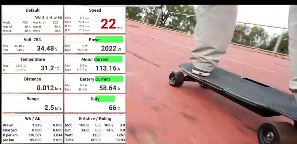
I'm expecting a max 2KW power draw, with a max of 57A per a motor (mainly for startup torque, they won't reach that current at full rpm),
hence the 40 Samsung 25R batteries, hopefully they don't explode. It will have a bluetooth interface connected to the ESC which will feed live
data to an android phone which can be logged for later reference. Here's a screenshot of the data interface overlayed onto a video.

R2%20VESC%20monitor_zps6jcvofym.png


It's an expensive hobby. I've spent well over a grand on parts already and it's nowhere near finished. Part of the reason I'm not as active as I used to be
because you develop new hobbies which are order of magnitudes more expensive... and before you know it you're eating noodles for the rest of the semester. :p
 

diachi

0
Joined
Feb 22, 2008
Messages
9,700
Points
113
"Hopefully they don't explode!"

No, that wouldn't be good! :crackup:

Interesting project, looking forward to seeing more. :)
 
Joined
Sep 20, 2013
Messages
17,423
Points
113
It ought to be something to see when it's done, Will. You must post photos when it's done and working.

 
Joined
May 12, 2013
Messages
751
Points
43
Last edited:

BowtieGuy

0
LPF Site Supporter
Joined
Oct 14, 2012
Messages
6,090
Points
113
It ought to be something to see when it's done, Will. You must post photos when it's done and working.

Great project Will, thanks for sharing, and yes, we will require more photos, and maybe a nice video of you speeding along on this badboy! ;)
:gj:
 

diachi

0
Joined
Feb 22, 2008
Messages
9,700
Points
113
This is my latest project, a (really very basic) high power constant current laser driver. Designed to be controlled (Current set will be adjustable from 0%-100% in 1% increments) and monitored (LD Current + LD Voltage) by an Arduino. Going for 20A with this first design, although you can really just keep adding power transistors to increase the limit. This is the first revision, it'll need some improvements (layout could do with some work) and probably some fixes. Ordered the components for the first prototype earlier today.

Would be nice if I could do double sided boards at home easily...

ABLDzDx.png


Next task is to add a couple TEC controllers and perhaps some other features.
 
Last edited:

diachi

0
Joined
Feb 22, 2008
Messages
9,700
Points
113
So, I guess this is to drive a pump diode for some SHG line output. Interesting.


Yep, I've got a couple 15-20W 808nm PM fiber coupled bars sitting around, ideal for end pumping a large chunk of Vanadate. That said - there's no reason this couldn't drive a bank of NUBM44s either.

Downside is that it's linear, so very inefficient. I can reduce losses in the current sense resistor by picking an appropriate resistor and turning down the Vref voltage, which can also be used to set the max operating current for a given resistor size. Still won't come close to a switching supply but I'm not quite ready to tackle one of those yet.

Can't seem to find any Molex KK 3.96mm pitch 7 pin connectors on eBay, may change that out for 2.54mm pitch or just go up to 8 pin 396. Or 6 pin and just leave the GND pin disconnected.
 
Last edited:
Joined
Sep 12, 2007
Messages
9,399
Points
113
Not that you asked, but there are several problems I can see already. I made a couple of these a few years back, but minus the digital.

Those traces aren't nearly large enough for 20A. The opamp you've chosen can't supply enough drive current unless you're using a particularly large darlington. At 20A, the darlington will be dissipating a MINIMUM of 40 watts. And that's only if you carefully select the input voltage. Even if you get a darlington rated for 120W, it's going to probably overheat unless you do something goofy like actively cool the heat sink it's on. There's no reason the rating of the cap across the diode needs to be as low at 5V. It is bad practice to leave unused op amp inputs floating, as it will often cause oscillations. It looks like you've attempted kelvin sensing of the laser diode voltage, but they should be AT the LD terminals, not a few mm over. Even then, it's not particularly helpful since your voltage drop on the power leads isn't nulled. Also, you need kelvin sense on the negative side of your shunt to get any decent accuracy.

there's no reason this couldn't drive a bank of NUBM44s either

*points to the 5V cap again*

Oh, and you'd need to scale down the voltage on the sense line. Arduinos don't last long with 40V on ADC pins.

I can reduce losses in the current sense resistor by picking an appropriate resistor and turning down the Vref voltage..

Yes, but this increases noise and risk of oscillations.
 
Last edited:

diachi

0
Joined
Feb 22, 2008
Messages
9,700
Points
113
Not that you asked, but there are several problems I can see already. I made a couple of these a few years back, but minus the digital.

No, but I appreciate the input from someone more experienced.

Those traces aren't nearly large enough for 20A. The opamp you've chosen can't supply enough drive current unless you're using a particularly large darlington. At 20A, the darlington will be dissipating a MINIMUM of 40 watts. And that's only if you carefully select the input voltage. Even if you get a darlington rated for 120W, it's going to probably overheat unless you do something goofy like actively cool the heat sink it's on. There's no reason the rating of the cap across the diode needs to be as low at 5V. It is bad practice to leave unused op amp inputs floating, as it will often cause oscillations. It looks like you've attempted kelvin sensing of the laser diode voltage, but they should be AT the LD terminals, not a few mm over. Even then, it's not particularly helpful since your voltage drop on the power leads isn't nulled. Also, you need kelvin sense on the negative side of your shunt to get any decent accuracy.

Trace sizes - I know, I increased the trace size in a second revision I made earlier, still not big enough, may order some heavier boards - or just slap a nice thick layer of solder on the high current traces if I'm being cheap and lazy. May also move the V+ input closer to where the current is needed most to reduce resistance losses in the traces.

Transistor drive current - Have considered swapping the transistor(s) out for MOSFETs for, at the least, easier driving. Does that sound like a good idea?

Waste heat - Lots of heat yes, but I have a real beefy TO-3 heatsink, easily big enough to handle the heat, may need some "forced" (probably more like a light breeze) air to keep it reasonable but it should be fine. Not using TO-220s with little clip on heatsinks here. Transistors I had planned on using are rated at 15A, I'd be using two for 20A, leaving them plenty of headroom. But as I said, may switch to MOSFETs anyway. I think I have some big MOSFETs in a parts bin somewhere...

5V Cap - Yep, my bad, forgot I had rated that at 5V, easy enough to swap out. Thanks for pointing that out.

Op-amp inputs - noted, thanks! :)


Voltage sensing - will move sense leads to LD outputs. That makes sense! Plan is to measure at LD+, LD- and RS+, all referenced to GND.
LD+ gives me the total drop across LD, transistor and sense resistor, LD- gives me voltage drop across the transistors and sense resistor and RS+ gives me the drop across the sense resistor. LD voltage drop is the difference between LD+ and LD-, which the arduino can calculate quite happily. Correct me if my thinking is off?


*points to the 5V cap again*

Forgot I had rated that at 5V - easy enough to swap out. Thanks for pointing it out.

Oh, and you'd need to scale down the voltage on the sense line. Arduinos don't last long with 40V on ADC pins.

Way ahead of you on that one at least, quickly threw together a design for a separate 10:1 voltage divider board for the arduino inputs earlier this afternoon, probably will put that on the driver itself in the next version. Max design input voltage will be around 40V yes, but lower in practice/actual use. It's inefficient enough as it is without driving at at nearly 40V! A 10:1 divider should do the job nicely.


Yes, but this increases noise and risk of oscillations.

Figured as much, and I plan on keeping it to a reasonable >1V for now. At least until I have some better test equipment and can test for noise/oscillations. That's also why I haven't attempted to add any sort of modulation input to this one.


Thanks again for your input, I appreciate it. See my responses in red...

Also building a nice big test load to put this thing through its paces before it goes near an LD. Friend has an O-scope, will likely borrow that just to verify that it won't kill any attached diodes as soon as I turn it on. No doubt this'll go through a few more revisions before it's ready, as I mentioned in my original post. It's far from perfect - the layout needs more improvement as does the actual design.
 
Last edited:


Top