Welcome to Laser Pointer Forums - discuss green laser pointers, blue laser pointers, and all types of lasers

LPF Donation via Stripe | LPF Donation - Other Methods

Links below open in new window

ArcticMyst Security by Avery

NUBM07E 465nm 2.9W Diode Test (Hitting 470nm+)

Joined
Sep 20, 2013
Messages
17,252
Points
113
RedCowboy, that is right. It is because the multimode is in the slow axis that this is what you are trying to correct for. If it were a single mode diode, there would be no need to go to these lengths to correct the beam geometry. Even though the fast axis is expanding faster than the slow one, it isn't as big a problem with, say a, 405nm diode.


Joined
Jul 10, 2015
Messages
9,799
Points
113
Oh yes, you are absolutely right, I'm just trying to identify the correct terminology, I know what to do with the beam by looking at it, but I have heard fast and slow explained more than 1 way.
 
Joined
Sep 20, 2013
Messages
17,252
Points
113
Well, if you are talking about the axis, it is the slow axis that needs correction. If you are talking beam geometry it is the strip, or the beam line that needs correcting. I'm not entirely sure that this is the preferred terminology, but it is the best I can come up with.
 
  • Like
Reactions: GSS
Joined
Jul 10, 2015
Messages
9,799
Points
113
Important note:

The wide stripe as viewed when looking straight down at the laser in your hand is not the orientation that you want when using Cyl correction because that ribbon/stripe at point blank from the module lens that would show on a brick at 1 inch as a horizontal line will diverge and appear as a vertical line in the far field, that is 12 feet away. This is not the orientation you want.

So when correcting a nubm44 your spot at 12 feet away will be a horizontal line when focused through a G2, however your spot at point blank shown on a brick right in front of the focused laser will appear vertical, it simply diverges faster on the narrow part of the observed line at point blank and becomes wider. This is what we want to correct.

It's easiest to simply focus your G2 to a sharp horizontal line at 12 feet, don't try to see what it's doing up close, it will be obvious when you see it through your glasses while aligning the pair.

So if I understand terminology wise, the narrow horizontal point blank axis that diverges the fastest is actually called the slow axis?
That's kind of opposite of how the very 1st diagram from PL explained it. But their drawing needed to be rotated 90 degrees.
It's the terminology that I'm not ever getting the same answer on, I will just draw pictures LOL.
fastslow2f_zpsispolvuf.png
 
Last edited:
Joined
Jan 5, 2011
Messages
417
Points
28
Oh yes, you are absolutely right, I'm just trying to identify the correct terminology, I know what to do with the beam by looking at it, but I have heard fast and slow explained more than 1 way.

I think a confusion starts when a lens is added to a system.

A bare SM diode is nicely defined by its fast and slow axes. There is even a special formula to get an emitter size (geometry) of a such diode having divergences on those axis.

When the lens is added to collimate (aka focus at infinity) a lot of things should be accounted - the lens focal length, its quality (like a simple lens vs ashperical or triple lenses), a diode's property to start "fast" and "slow" axis beams at a different location (astigmatism).
Initially the diode fast axis divergence define the beam at the module exit as elliptical. Farther the laser diode larger emitter size on slow axis kicks in and the beam looks like a stripe on the wall.
 
Joined
Jul 10, 2015
Messages
9,799
Points
113
OK so if we take the lens out and shine the diodes output on the wall ( clamped down in a vise all the time never changing the diodes orientation ) at 5 feet we get this.

===============================================
===============================================
===============================================

when focused through a G2 or 3 element we get this......l....... minus the dots.

So in the raw output the wide portion is the faster diverging axis, however if viewed through a focused lens at 5 feet the thin part is the faster diverging axis that turns into this: ------------------- in the far field.

But are they called that based on what they do? or some other parameter?

A rose by any other name is still a rose and I know what to do with it, the terminology is the question.
 
Last edited:
Joined
Sep 20, 2013
Messages
17,252
Points
113
Yeah, lazeristas pointed out the main thing I should not have omitted from my explanation. If using an aspheric lens, like the G-2, focused to infinity, the strip, stripe, line, is the slow axis on a MM diode.
 
Joined
Jul 10, 2015
Messages
9,799
Points
113
Ok.....industrial diodes talk of FAC fast axis correction, and we are in fact correcting the faster diverging axis.....Is that axis called the slow axis?
Regardless of how it performs? i.e. diverging faster.

I try to use the terms faster diverging and horizontal diverging axis to explain, because a lot is lost in translation.

It's like saying passenger side or driver side because right and left depends on where you're standing.

So to reiterate, a nubm44 focused through a G2 into a wide short horizontal line at 15 feet.
The horizontal axis as seen is faster diverging, but is it called the slow axis anyway?
 
Last edited:
Joined
Jan 5, 2011
Messages
417
Points
28
But are they called that based on what they do? or some other parameter?

A rose by any other name is still a rose and I know what to do with it, the terminology is the question.

"Fast" or "slow axes" terms are used for a laser diode without any additional optics. See your posted pictures where you really can distinguish fast and slow spreading of the beam (without any lens!!!)

There is another terminology to describe axes of the far field pattern: parallel and perpendicular to the LD junction (while it is confusing (relative thing) actually it is a correct way as some diodes have very similar divergences on both axis.)
 
Joined
Jan 5, 2011
Messages
417
Points
28
Ok.....industrial diodes talk of FAC fast axis correction, and we are in fact correcting the faster diverging axis.....Is that axis called the slow axis?
Regardless of how it performs? i.e. diverging faster.

I try to use the terms faster diverging and horizontal diverging axis to explain, because a lot is lost in translation.

It's like saying passenger side or driver side because right and left depends on where you're standing.

So to reiterate, a nubm44 focused through a G2 into a wide short horizontal line at 15 feet.
The horizontal axis as seen is faster diverging, but is it called the slow axis anyway?

"FAC fast axis correction" - A lot of diode has a very large divergence on a "fast axis" (again no focusing lens nearby). Adding a special cylindrical lens the divergence is reduced and matched with the slow axis.


If you add a laser module and a laser diode there will be less confusion:
The horizontal axis of a laser module (a laser diode with a lens) is faster diverging (if orientated appropriate), but it is the slow axis of a laser diode anyway. Reason: you see enlarged the laser diode emitter on the wall.
 
Joined
Sep 20, 2013
Messages
17,252
Points
113
"FAC fast axis correction" - A lot of diode has a very large divergence on a "fast axis" (again no focusing lens nearby). Adding a special cylindrical lens the divergence is reduced and matched with the slow axis.


If you add a laser module and a laser diode there will be less confusion:
The horizontal axis of a laser module (a laser diode with a lens) is faster diverging (if orientated appropriate), but it is the slow axis of a laser diode anyway. Reason: you see enlarged the laser diode emitter on the wall.

This is an excellent and concise explanation. :thanks:
 
Joined
Jul 10, 2015
Messages
9,799
Points
113
Has anyone powered up a NUBM07E in a heat sink with the Gball in place and if so do you by any chance have a pic of the output?

I want to use cylindrical correction right after the Gball lens, or possibly an expander setup like Alaskan uses only in as compact of a build as possible.

Any pics at all would be appreciated, so far styropyro's block video is all I have to go by.

Thanks.
 
Joined
Oct 6, 2015
Messages
1,355
Points
113
Has anyone powered up a NUBM07E in a heat sink with the Gball in place and if so do you by any chance have a pic of the output?

I want to use cylindrical correction right after the Gball lens, or possibly an expander setup like Alaskan uses only in as compact of a build as possible.

Any pics at all would be appreciated, so far styropyro's block video is all I have to go by.

Thanks.

am thinking of getting 1 in and use the stock lens did anyone do a build yet !
can we use the 3elm lens after the stock lens !?
 
Joined
Jul 10, 2015
Messages
9,799
Points
113
That last post was over 3 months ago, lol.

I now know the NUBM07e with Gball on makes a 25 x 50 mm big spot at 5 meters.

For comparison a NUBM06 makes a 25 x 6 mm line at 5 metes through it's Gball.

All the nubm's do better with the Gball off and a G7 or 3 element as far as spot size.
 
Joined
Oct 6, 2015
Messages
1,355
Points
113
That last post was over 3 months ago, lol.

I now know the NUBM07e with Gball on makes a 25 x 50 mm big spot at 5 meters.

For comparison a NUBM06 makes a 25 x 6 mm line at 5 metes through it's Gball.

All the nubm's do better with the Gball off and a G7 or 3 element as far as spot size.

I just posted one to sell NUBM07E and 4.5A since am trying to get one with gball to see the diversity !
 
Last edited:
Joined
Jul 10, 2015
Messages
9,799
Points
113
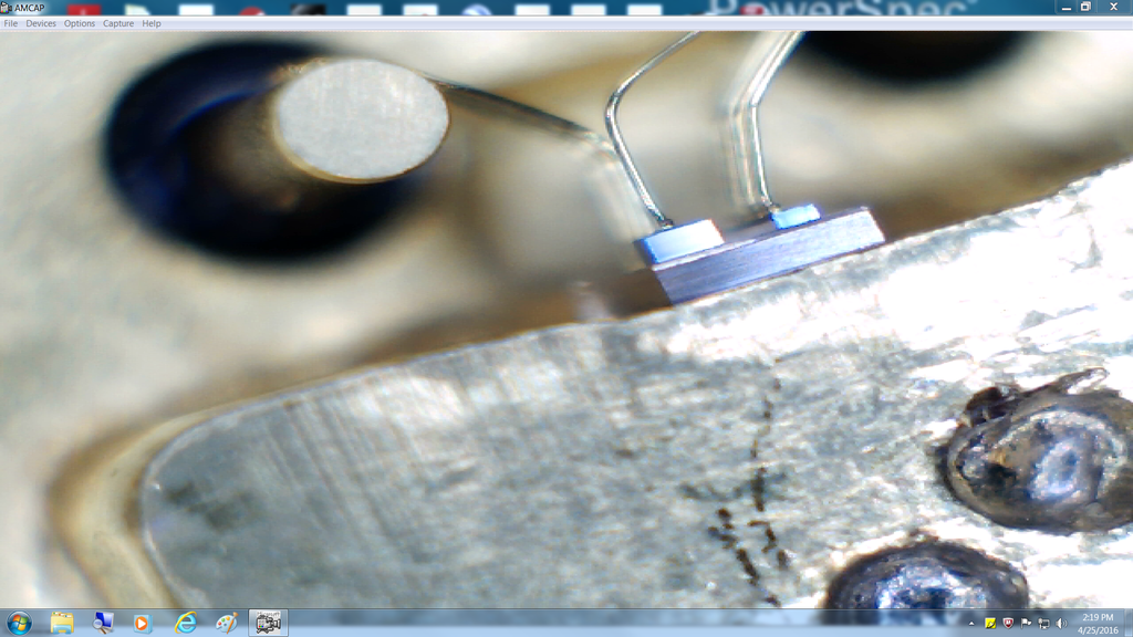
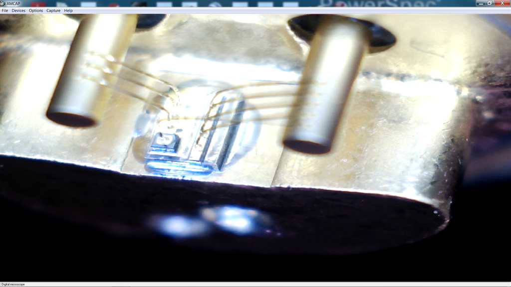
The window on the front of the emitter just like the can windows don't like to be contaminated.

That's 1 factor, another may be humidity.

Looking at the emitter I don't know that oxygen could get at the gain medium, I think it has a tiny window, but contamination is an issue.

The emitter is on the right, I think it has a window, but it likes to be clean or it will pop/crack.

Capture_04252016_141915_zpsiytfqlai.png


Capture_04252016_141658_zpsbglol4tz.png
 
Last edited:


Top