Welcome to Laser Pointer Forums - discuss green laser pointers, blue laser pointers, and all types of lasers

LPF Donation via Stripe | LPF Donation - Other Methods

Links below open in new window

ArcticMyst Security by Avery

FREE DIY open source BOOST driver!!! Tested & working!!

Joined
Aug 30, 2008
Messages
6,891
Points
83
Hey Moh...

Are you also planning to sell Driver Kits... Just the board
and unmounted parts for the members that might want
to roll their own...:thinking:


Welcome to my world....;)


Jerry
probably. makes it easier on me.


Blord

0
Joined
Dec 24, 2007
Messages
5,356
Points
0
Yes, I would like that too. Just throw the components in a bag and I will figured it out.
 
Joined
Sep 20, 2008
Messages
17,622
Points
113
No need to figure anything out. The parts should be identified
on the PCB and the schematic tells you which part is
which..

@Moh...
Yeah... that's what I thought...


Jerry
(11800-448-39768)

You can contact us at any time on our Website: J.BAUER Electronics
 
Last edited:

rhd

0
Joined
Dec 7, 2010
Messages
8,475
Points
0
No need to figure anything out. The parts should be identified
on the PCB and the schematic tells you which part is
which..

Though you might need a magnifying glass to read the resistor values! (if they're even indicated on such low resistance SMD components).

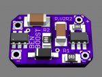
Alright, so I forked the design again, essentially just to make it easier to heatsink. I'm forking from the OVP board though, because I *really* don't care about OVP. With a $30 Flex, I can see wanting to make sure your board survives if a diode somehow dies and goes open-circuit. But at <$5 to put these together, if a diode dies and the circuit goes open and then kills the driver, I'll care about the diode death a lot more than the $5 driver death ;) And in building, I'm really not likely to power them up without a diode attached via soldered leads.

So, I wanted to ease the heatsinking, and thus wanted to move the heat producing components to the board edges. I stuck with 1206 caps so that they'd be thinner. I retained the two-set-resistor approach.

attachment.php
 

Attachments

  • LD Ben Boost, RHD Fork V2 R2.jpg
    LD Ben Boost, RHD Fork V2 R2.jpg
    149.7 KB · Views: 760
  • LD Ben Boost, RHD Fork V2 R2.zip
    7.9 KB · Views: 61
Last edited:
Joined
Sep 22, 2010
Messages
1,358
Points
48
I think they're going to be around $12.

Excellent news. The price is very reasonable for those of us who can't solder SMDs to save our lives. Now I can finally use that saik kit I bought from you ages ago. I've been trying to figure out how to power one of your 1.8A mohgasm drivers with someting that'd fit in it. Two of these set to ~900ma and the extra 26650 (or was it a 26600?) should do the job nicely. Its massive heatsink should be plenty big for both the diode and drivers.
 
Joined
Aug 14, 2011
Messages
1,109
Points
0
Excellent news. The price is very reasonable for those of us who can't solder SMDs to save our lives. Now I can finally use that saik kit I bought from you ages ago. I've been trying to figure out how to power one of your 1.8A mohgasm drivers with someting that'd fit in it. Two of these set to ~900ma and the extra 26650 (or was it a 26600?) should do the job nicely. Its massive heatsink should be plenty big for both the diode and drivers.

Yep, me too, I've got a Saik inbound from DX. Get some of those Saik heatsinks ready to go on your site, Moh! *ahem* :D
 
Joined
Aug 14, 2011
Messages
1,109
Points
0
You'll need to install a lathe in the back of the ambulance...:D

Jerry

Haha Can you imagine the poor guy getting transported to the ER, and Moh busting out some heatsinks in the back while the ambulance zig zags through traffic?! :crackup:
 
Joined
Feb 12, 2012
Messages
237
Points
0
i wounder if insurance covers damage from flying aluminum.:crackup::crackup::crackup:
 
Joined
Jan 14, 2011
Messages
3,816
Points
63
Hey everyone. So today I have a physics lab (I'm a physics/math double major) on AC circuits, meaning that I get to work with an O-scope. The good part about this is that I can bring in my own rendering of this circuit and test it out there in some spare time!

My circuit is nearly identical to the one that they did except I am using a 6.8uH inductor (only large enough inductor I have on hand and it works well enough) and I changed the layout so it fits on a single-sided 16.2mm round PCB. Anyway, I'm bringing my test load and I will use the PSU there, and all should go swimmingly!
 
Joined
Dec 27, 2011
Messages
2,062
Points
48
My circuit is nearly identical to the one that they did except I am using a 6.8uH inductor (only large enough inductor I have on hand and it works well enough) and I changed the layout so it fits on a single-sided 16.2mm round PCB. Anyway, I'm bringing my test load and I will use the PSU there, and all should go swimmingly!

Famous last words! Lol!

Good luck and let us know how it turns out.

P.S. Your degree is very similar to mine! Engineering Physics with a minor in Math - funny thing is that I hated math in high school, but differential equations and calculus were fascinating! I've forgotten nearly all of the math now... :yabbem:
 
Joined
Jan 14, 2011
Messages
3,816
Points
63
Will do. Hopefully there isn't much ripple - no one likes a rippling circuit!


Top