Welcome to Laser Pointer Forums - discuss green laser pointers, blue laser pointers, and all types of lasers

Buy Site Supporter Role (remove some ads) | LPF Donations

Links below open in new window

FrozenGate by Avery

Laser printer polygonal mirror assembly

Joined
Feb 26, 2010
Messages
50
Points
0
Is anybody here able to decrypt this pinout schematics: Service manual Epson AcuLaser C1100 | RefillBROS
All I can figure out is if I connect +12v (it really says that you should connect +24V but I don't dare yet...) to "INTERLOCK assembly" and then ground it.
Results that I'm getting is if I'm connecting "SCANNER MOTOR ON (L)+5VDC" to just that 5 VDC I get nothing,
but if I on the other hand connect it to ground whole mirror assembly will jump start and then STOP in like a millisecond.
I've tried to touch "SCANNER MOTOR CLOCK" pin to both negative and positive without any results while having connected Scanner motor on...

Any suggestions? I'm really confused about this assembly...

You're going to need a pulsed clock source for the "Scanner Motor Clock" pin to make the thing scan. The "Scanner Motor On" will enable scanning, and the clock is, I suspect, going to control the speed somewhat.
 
If you can pull the mirror off of the motor shaft I suggest you put it on a normal DC motor. It sounds like the motor is a stepper motor or something.
 
No, they are not stepper motors, in fact they are 3-phases brushless motors with integrated driver and power ..... moves much more smooth than steppers ..... usually, if you don't need the synchro, SOS and control signals that are used for image making in a printer (basically, if you just need it as a scanning motor for "liquid sky" or similar), you just need to find the GND, +V (that in 90% of the cases is 5V, and sometimes 12V), and the "remote on" signal (also here, in 90% of the cases, it's a simple signal that must be tied to GND or to VCC for start the motor)

Some assemblies can have also a "clock" input, that permit you to change the speed at your pleasure, but this depend from the manufacturer and from the general circuitry of the machine ..... without some good macros of the PCB, is hard also just start to guess it .....

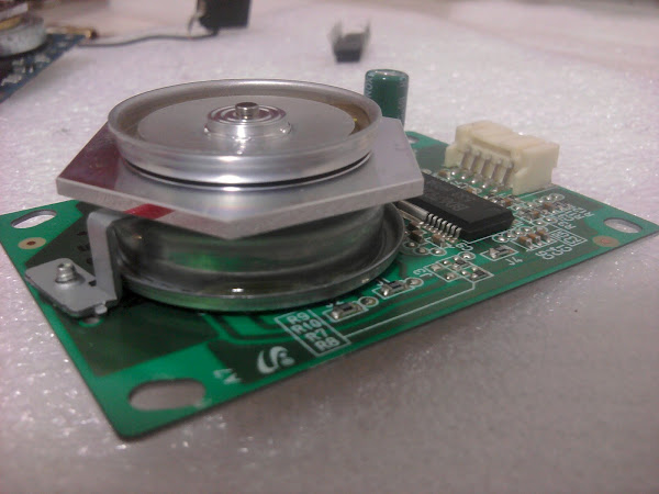
As example, look this one:

attachment.php


As you can see, there's just one "relatively big" electrolitic capacitor, so, this is in parallel with the main power supply, and ofcourse the polarity is the same (+V on the positive and GND on the negative), so a little bit of reverse engineering (following the trachs from the capacitor with a multimeter, or with the eyes ;)), gives you the power pins, and the voltage of the capacitor gives you an idea about the voltage (i mean, if the capacitor is rated 10 or 16V, probably is a 5V power supply, if is rated like 25V or similar, can also be 12V) ..... anyway, always start with 5V, for safety.

Then you can have 2 possibilities ..... or the motor start to spin alone, and in this case you're ok, or not, and this mean that you need also a remote on signal ..... in this case, take a wire and a 100 or 200 ohm resistor, or similar value, and start to connect the other pins, one by one, to the VCC and to the GND, and see if the motor start to spin ..... if yes, then you have a "trigger input", that turn it on and off ..... if not, there's the possibility that it have a "clock input", that need a frequency, and this frequency changes the speed ..... in this case you need to build aan oscillator for test more.
 

Attachments

  • polymirrormotor.jpg
    polymirrormotor.jpg
    218.6 KB · Views: 6,215
If you do need a clock source to get it going, a simple 555 timer circuit should probably do the trick, depending on the necessary clock frequency.
 
I ripped another motor with a polygonal mirror on it from another laser printer and I got it to spin up by first connecting "Motor enable" or smth similar in datasheet to negative, and then "Motor clk" to minus (!!!) 5 volts.

However I will try HIMNL9's approach on that tricky motor when I get some free time...

These motors will be used mainly for liquid sky effect and maybe making a laser oscilliscope sometime too.

Tips: Getting broken laser printers is quite easy, just go and ask your local computer store! :D
 
Is anybody here able to decrypt this pinout schematics: Service manual Epson AcuLaser C1100 | RefillBROS
All I can figure out is if I connect +12v (it really says that you should connect +24V but I don't dare yet...) to "INTERLOCK assembly" and then ground it.
Results that I'm getting is if I'm connecting "SCANNER MOTOR ON (L)+5VDC" to just that 5 VDC I get nothing,
but if I on the other hand connect it to ground whole mirror assembly will jump start and then STOP in like a millisecond.
I've tried to touch "SCANNER MOTOR CLOCK" pin to both negative and positive without any results while having connected Scanner motor on...

Any suggestions? I'm really confused about this assembly...

I apologize for the old thread, but the C1100 have a polygon mirror?
I can have a lot for free!

Regards
 
Almost any laser printers (NOT the ones called LED laser printers) have a similar assembly ..... they can vary alot in shapes and sizes, but you have a good 95% of probability that Epson C1100 have them inside.
 
Almost any laser printers (NOT the ones called LED laser printers) have a similar assembly ..... they can vary alot in shapes and sizes, but you have a good 95% of probability that Epson C1100 have them inside.

Hi, you are right!, I found an exploded schematics of C1100 and they have the polygon mirror inside.
 
No, they are not stepper motors, in fact they are 3-phases brushless motors with integrated driver and power ..... moves much more smooth than steppers ..... usually, if you don't need the synchro, SOS and control signals that are used for image making in a printer (basically, if you just need it as a scanning motor for "liquid sky" or similar), you just need to find the GND, +V (that in 90% of the cases is 5V, and sometimes 12V), and the "remote on" signal (also here, in 90% of the cases, it's a simple signal that must be tied to GND or to VCC for start the motor)

Some assemblies can have also a "clock" input, that permit you to change the speed at your pleasure, but this depend from the manufacturer and from the general circuitry of the machine ..... without some good macros of the PCB, is hard also just start to guess it .....

As example, look this one:

attachment.php


As you can see, there's just one "relatively big" electrolitic capacitor, so, this is in parallel with the main power supply, and ofcourse the polarity is the same (+V on the positive and GND on the negative), so a little bit of reverse engineering (following the trachs from the capacitor with a multimeter, or with the eyes ;)), gives you the power pins, and the voltage of the capacitor gives you an idea about the voltage (i mean, if the capacitor is rated 10 or 16V, probably is a 5V power supply, if is rated like 25V or similar, can also be 12V) ..... anyway, always start with 5V, for safety.

Then you can have 2 possibilities ..... or the motor start to spin alone, and in this case you're ok, or not, and this mean that you need also a remote on signal ..... in this case, take a wire and a 100 or 200 ohm resistor, or similar value, and start to connect the other pins, one by one, to the VCC and to the GND, and see if the motor start to spin ..... if yes, then you have a "trigger input", that turn it on and off ..... if not, there's the possibility that it have a "clock input", that need a frequency, and this frequency changes the speed ..... in this case you need to build aan oscillator for test more.

I did all these but, even clocked input. till no run. The controller is BD6792FM. Can enyone tell me in which printer i can find an hexagon mirror or an octagon mirror.
 
Last edited:
SurplusShed sells some Sharp laser printer assemblies cheap - I think like $15 cheap. They've got multi-sided mirrors like those above inside them. Also, similar brushless motors. (PITA).
 
I did all these but, even clocked input. till no run. The controller is BD6792FM. Can enyone tell me in which printer i can find an hexagon mirror or an octagon mirror.

Do you have pics of your unit ?

Also, 95% of the laser printers (EXCEPT the ones called "LED" laser printers) have one of these units, more or less similars.
 
Do you have pics of your unit ?

Also, 95% of the laser printers (EXCEPT the ones called "LED" laser printers) have one of these units, more or less similars.

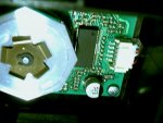
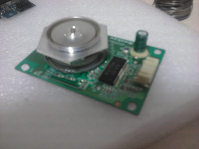
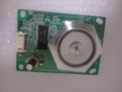
Yes i have some pics,
2011-05-06+14.53.26.jpg


2011-05-06+14.53.31.jpg


It will be helpful if u can name some printers that have hex or octagon mirror instead of 4 faced polygon. Thank you.

2011-05-06+15.08.34.jpg
 
Last edited:
It will be helpful if u can name some printers that have hex or octagon mirror instead of 4 faced polygon.
 
The pics a re a bit too blurred ..... anyway ..... where you see that electrolitic capacitor, connecting 5 (or 12) V at its pins (or to the connector pins that go to it) with the right polarity, it must spin .....

If not, try to connect the other pins (one at a time), to +V or -V pins, for find the "confirmation" signal (for do this, use a piece of wire with a 500 ohm / 1 kohm or similar resistor) ..... ofcourse, WITH the + and -V still connected to the pins where the capacitor is connected ..... those assemblies are usually powered with 12V, but few ones had also the power section at 5V, for this i suggested to start with 5V, and switch to 12V if nothing happens with 5V .....

There is also the possibility that your assembly is broken or nonfunctional, if nothing happens with any combinations.

About the names, i can't imagine ..... i mean, i dismantled epson, samsung, HP and canon laser printers and always found 6-faces (and rarely 8-faces) mirrors, but NEVER a 4-faces one :confused:
 
If these are anything like the ones sold on Surplus Shed, they'll have just a Power, Ground, and Enable, and they take care of all the timing and powering. You will, however, need a higher voltage source for the motors. I found 18V worked best. The enable pin at its floating range seems to allow you some linear control of the speed. Here is the pin-out from the SS one I tested.


Back
Top