Welcome to Laser Pointer Forums - discuss green laser pointers, blue laser pointers, and all types of lasers

LPF Donation via Stripe | LPF Donation - Other Methods

Links below open in new window

ArcticMyst Security by Avery

X-boost v7 micro driver question

icah93

0
Joined
Feb 5, 2009
Messages
73
Points
8
Hi Members,

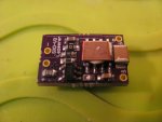
recently I rebuilt my 445 project and I exchanged my linear driver to the X-boost v7 micro (capable of ~1.8A).
I am powering it from a 18650 cell.
Everything is fine till ~30 seconds, then the light begin flickering, starting slow, then getting faster.

My driver is not heatsinked yet, and set to 1.5A.
The circuit was measured before mounting it to the host, and 1.5A flew through the diode for sure.

Is that possible that the flickering is caused by the inbuilt thermal protection?
Have anybody experienced the same behavior with this driver in the past?


Radim

0
Joined
Aug 17, 2016
Messages
1,458
Points
83
Yeah, might be the case. And are you sure you draw current within the specs? Aren't you overloading it with diode peak current? It might be also overload regulation.
 

icah93

0
Joined
Feb 5, 2009
Messages
73
Points
8
Thanks, guys. By out of regulation you mean because of overload or because of heat?
Overload should not be possible as I measured the current before mounting and it was constant.
The diode has sufficient cooling.

Out of regulation because of driver overheating is possible yes, and as soon as my thermal adhesive
arrives I shall cure that.
First I simply believed that @1.5A (<1.8A) the driver overheating should not be an issue, according to
earlier posts in that driver's thread.

On the other side, I must admit that the driver is soooo tiny (around 12x8mm as I remember)
so overheating must be an issue here.
I wondered it to even work correcly for the first 30-40 seconds without having the heatsink on it.

However it is still not clear for me how to properly put a heatsink on it.
The components surrounding the chip are as tall or taller than the chip itself
and if I stick any heatsink to it, it may short the other components easily.
The chip itself is only about 3mmx3mm, so I do not see any possibility to get only the chip heatsinked,
but somehow the whole side of the pcb should be treated by a thermal adhesive.

How did you solve that guys formerly?
 

Radim

0
Joined
Aug 17, 2016
Messages
1,458
Points
83
Did you test it with diode or dummy load when measuring current? Likely it is thermal protection, still I would expect complete shut down in this case and function recovery as soon as it is cool enough. Anyway I'm not sure if actual power switch (amplifier or MOSFET) is integrated in the IC or external. The most heat is produced on this switch AFAIK.

Look for computer and electronic components shop, there should be insulating and thermal pads available (sticky design), you can put it on back/bottom side of the driver and fit it to heatsink.
 
Last edited:

icah93

0
Joined
Feb 5, 2009
Messages
73
Points
8
Did you test it with diode or dummy load when measuring current?

Look for computer and electronic components shop, there should be insulating and thermal pads available (sticky design)

I did not test it with dummy this time as I did not want to make any possible mistake and harm the driver.
I simply wired the diode together with the driver, host and current meter in one circuit and measured the current.
BUT, I did not keep the measurement for more than 5-10 seconds, so culpa mea.

Yes this was my intention exactly and I remembered to have a thermal pad @home but I was mistaken, the pad was not sticky :-( so I need to order one.
Still, it will not be such a good solution as a thermal paste, I think.
I guess these pads do not have as good thermal conductivity as the paste.
 

Radim

0
Joined
Aug 17, 2016
Messages
1,458
Points
83
I did not test it with dummy this time as I did not want to make any possible mistake and harm the driver.
I simply wired the diode together with the driver, host and current meter in one circuit and measured the current.
BUT, I did not keep the measurement for more than 5-10 seconds, so culpa mea.

Yes this was my intention exactly and I remembered to have a thermal pad @home but I was mistaken, the pad was not sticky :-( so I need to order one.
Still, it will not be such a good solution as a thermal paste, I think.
I guess these pads do not have as good thermal conductivity as the paste.

Ah, in that case it still might be overload at diode peak (after 5-10 seconds). Diodes are semiconductors, with higher temperature, there is higher current (opposite relation to conductors).

And paste should be better IMO, however I'm not sure if it is not electrically conductive, in that case still some insulation is needed to prevent shorts.
 
Last edited:

icah93

0
Joined
Feb 5, 2009
Messages
73
Points
8
Radim, I do not understand, I am not an electronics expert but how can be there
an overload if the max. current is set to a fix 1.5A?
The driver simply does not provide more current to the diode, so I am not sure
how the diode current hunger influence the driver behavior in this case.

As the diode heats up it wants more current, that is clear.
The driver does not provide more current, but max. 1.5A.
By the raising current huger the diode will never want less than 1.5A,
so how comes here the flickering?
If the current would go between the max. 1.5A and let's say less, like 1.2A
or 1.0A then back to 1.5A I imagine there could be flickering.
But this is not a case here.
The only think that can happen is that when the driver reaches the maximally
set 1.5A, it drops the current for some (???) reason to less for a short moment,
causing flickering.
In this case, the driver is badly designed, is not it?

Or it is intentional, but in that case I can only imagine blaming heat protection.

Sure I can be mistaken with this, so correct me :)
 

icah93

0
Joined
Feb 5, 2009
Messages
73
Points
8
One more reason comes to my mind, when the battery is not capable
of providing enough current, but this is not the case here, as it is not protected
and capable of deliver 20-30A current easily.
 

Radim

0
Joined
Aug 17, 2016
Messages
1,458
Points
83
It is due to variable resistance of the diode as it heats. Look for some time/current characteristics. It tries to draw more at peak, but driver is limited, therefore it behaves as a short circuit for a while. The driver tries to charge the output capacitor on the regulator, but this capacitor discharges too fast (overload) and overall voltage on output drops, here the regulator senses it through feedback loop and cannot deliver more since it is limited at 1.5 A. If you are sure diode goes to 1.5 A, you should have regulator delivering slightly more to prevent flickering IMO. Also make sure diode is heatsinked well, since it will take all the current untill it dies. Check datasheet for max. current.

Hopefully this clarified it a bit. ;)

Edit: Li Ions are also very sensitive to temperature - if too low, they deliver far less current due to higher internal resistance. Also protection circuitry on batts can cut it off. But not the case here.
 
Last edited:

icah93

0
Joined
Feb 5, 2009
Messages
73
Points
8
Thanks for clarification.
It is much clearer now.

The diode is an M140 capable of lasing from 0.3A to 2.0A,
but I do not want to drive it with more than 1.5A for safety.
My battery is a Panasonic NCR18650PF, capable of delivering max. 10A current, so I was mistaken with the 20A.
The host is a WF501 with a large alu heatsink.

As I am pretty sure that the diode does not overheat but after about 40 seconds it is still cold to touch.
I am not sure how warm should be the alu heatsink after 40 seconds,
if driven the diode with 1.5A.
Maybe the 12mm diode module does not touch the alu heatsink well,
and the diode starts overheating, causing the voltage drop?
Previously I used an LM317 based driver, diode was driven at around 0.7A.
I could leave it on for 2-3 minutes without any problem.

The flickering is present either in the room or outside (68F,32F).
I shall try to make a short video about it.
 

Attachments

  • wf501.JPG
    wf501.JPG
    256.3 KB · Views: 18
Joined
Mar 27, 2011
Messages
507
Points
63
I sure 100% that it is an overheat protection of the IC
Many power management IC are equipped with thermal protection which will shutdown the IC when reach a typical temperature of 150°C
And will continue the operation when it cools down to certain threshold below 150°C

Even if you are not running the driver 1.8A, outputting 1.5A could cause some heat due to boost topology. With any Boost driver its going to get hot regardless of the output current.
 
Joined
Dec 15, 2014
Messages
6,783
Points
113
Hi,
Yes a small piece of copper is what i use on the IC's on my X Drives and SXD's . X Drives get a heat sink at 1.5A and above same for the SXD's. X Boosts get one over 1A .

Rich:)
 

Attachments

  • IMG_2658.JPG
    IMG_2658.JPG
    147.1 KB · Views: 27
  • IMG_1721.JPG
    IMG_1721.JPG
    149.6 KB · Views: 33

icah93

0
Joined
Feb 5, 2009
Messages
73
Points
8
Thanks so much for your answers!

So first I try to heatsink the chip somehow and I hope it solves the issue.
 
Joined
Dec 15, 2014
Messages
6,783
Points
113
Hi (#,
Were are you located on the globe? Slip it into your Avatar,
Now if you need some copper sinks i will cut and send them free like in the post sent ,
Let know

Rich:)


Top