Welcome to Laser Pointer Forums - discuss green laser pointers, blue laser pointers, and all types of lasers

LPF Donation via Stripe | LPF Donation - Other Methods

Links below open in new window

ArcticMyst Security by Avery

Whats wrong with this pic?

Joined
Apr 9, 2008
Messages
33
Points
0
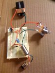
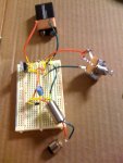
Hey fellas look I'm working on building my first laser and I followed the how to build a laser diode driver video on metacafe. I got everything done and hooked up to my power source and my diode. Bellow is a pic of what I'm lookin at. The diode is in the aiziz module but I'm not sure if its centered perfectly. Its also not completely pushed into the top half of the module, just enough not to come out when I pull on it. I have tried using 9volt duracell and energizer batteries I have tried two AAA with a combined voltage of 3volts and I have tried six volts. I am getting a small red dot when I power it up but its not nearly as strong as it should be for a 16X diode and it certainly isn't gonna burn anything anytime soon :'(. How do I get more power out of this? Do I need a more powerfull battery, should I remove one of the parts on the circuit board? Please help!
 

Attachments

  • whatswrong.jpg
    whatswrong.jpg
    86.8 KB · Views: 108


Joined
Jul 24, 2007
Messages
2,749
Points
0
Your picture is a bit fuzzy, I have marked which wires should join to others in yellow, can you confirm that this is how it is connected?

As that is a red LD you need to swap that 9v for at least 7.2 volts of AA batteries or a couple of CRC123A's. The 9v will not put out enough ma's over any period of time.
Have you tested the circuit as suggested here?
http://www.laserpointerforums.com/forums/YaBB.pl?num=1197651171

Give us some figures from the testing then we may be able to help a bit more.

Regards rog8811
 

Attachments

  • like_this-Q.jpg
    like_this-Q.jpg
    192.6 KB · Views: 102
Joined
Apr 9, 2008
Messages
33
Points
0
Hey I have all of my corrections made correctly. As for the batteries. I have 4 CR123As at my house and I can use those but I would I connect the two wires here to four of these batteries? Is there some kind of holder for these batteries that I could use? Thanks for the help because I thought my power source was the issue as I had only seen CR123A or AA batteries used for this but I wasn't sure how to connect the two wires to multiple batteries. If you know of a place where I could get the CR123A battery holder within a week that would be fantastic!
 

drlava

0
Joined
Mar 7, 2007
Messages
1,152
Points
0
A blown diode has a faint red glow (small red dot) that isn't an even pattern with the brightest spot in the center. Also, it is important that the diode be pressed in all the way to the module so the heat can be drawn out of it most efficiently. Otherwise it could overheat and blow the diode. Finally the module itself needs to be heatsunk if you're going to run it for longer than a few seconds at a time.
 
Joined
Jul 24, 2007
Messages
2,749
Points
0
20 seconds on the forum search found this....
http://www.digikey.com/scripts/DkSearch/dksus.dll?Detail?name=BC2/3AE-ND

Or you can do as I do if I am in a hurry, take a file to the ends of the batteries, file through the plating, solder a wire between the + end of one battery to the - end of another. A wire from the unused + to a switch of some sort (any switch will do) wire from the other side of switch to your bread board, then the last wire from the unused - to the bread board and you are good to go....

Have you tested the circuit as suggested, it is important to do so, then you can diagnose the problem more easily.

Regards rog8811

*Edit, I found this picture I did for someone else which shows how to wire it up (switch is in neg lead not pos as described above either way is OK)
 

Attachments

  • wire_bats01.jpg
    wire_bats01.jpg
    43.9 KB · Views: 127
Joined
Apr 9, 2008
Messages
33
Points
0
I can't test my board because I dont have 4 diodes but I tried hooking up two CR123A batteries and still had basically the same effect. I have a clear dot (in the dark) but as I move closer or farther the dot gets larger and blury. Is there any way I can get more power out of this? By the way, in the guide that I used I have a 25 ohm pot in place of the 100 ohm resistor that you had in your pic. would that change anything? also would I get any more power if I were to remove my 35 volt capacitor? This is a mess. Thanks for the help.
 

chido

0
Joined
Dec 4, 2007
Messages
1,918
Points
0
You don't need the 4 diodes, you use those to make sure the driver is working properly before using the actual LD. But since you already used the LD and we know it's working, get a 1 ohm resistor and place it between the positive leg of your diode and the positive wire coming from the driver, then grab your multimeter, set it to mV and place the positive probe between the resistor and the driver and the negative probe between the resistor and the LD. Then just measure the current. In this case 1mV = 1mA.

but as I move closer or farther the dot gets larger and blury
Have you tried focusing it? ;)

in the guide that I used I have a 25 ohm pot in place of the 100 ohm resistor that you had in your pic. would that change anything?
You'll be fine, in fact, the 25 ohm is better since it won't be as sensitive as the 100 ohm pot.

also would I get any more power if I were to remove my 35 volt capacitor?
Don't remove the capacitor, it helps prevent spikes from getting to the LD and it won't give you more power if you remove it.


Top