Welcome to Laser Pointer Forums - discuss green laser pointers, blue laser pointers, and all types of lasers

Buy Site Supporter Role (remove some ads) | LPF Donations

Links below open in new window

FrozenGate by Avery

what did I do wrong?


Not easily... Did the pins break off flush to the back of the diode can or is there something still left?
 
wait you have 500 posts and you are saying you should quit? Is this your first DIY?

Quote from dave: "you haven't lived until you break a $300 diode"

So dont give up..Take it very slowly and if you need to solder one pin and go watch tv for a while then solder the other..just relax while you are doing this...it should be fun not painful...thats why its a hobby...

But PLEASE dont give up! Seriously 1 phr803t isnt that bad...just try again

:D My diode graveyard :D:

4XStonetek Diodes (20 dollars each)
1Xphr803t(15 each)

95 dollars just by mistakes lol
 
I need my money for other things, laser diodes is pretty low on the list.

And my pins came flush off.
 
Hmm, from your story, I'm considering rigging up a pin and socket mount when I build my 803t pointer. I'll solder the sockets directly to the driver, then plug the diode into the sockets, so it can be easily removed, yet secure during normal use.
 
If you don't wanabe a laserdon'twanabe you could try to repair it, it is not easy, it is not robust, but can be done.

!) Use wire wool to clean up the back of the diode and the pin stubs.
2) If you want to put this in a host where the negative return is  through the flashlight body, locate the negative stub.
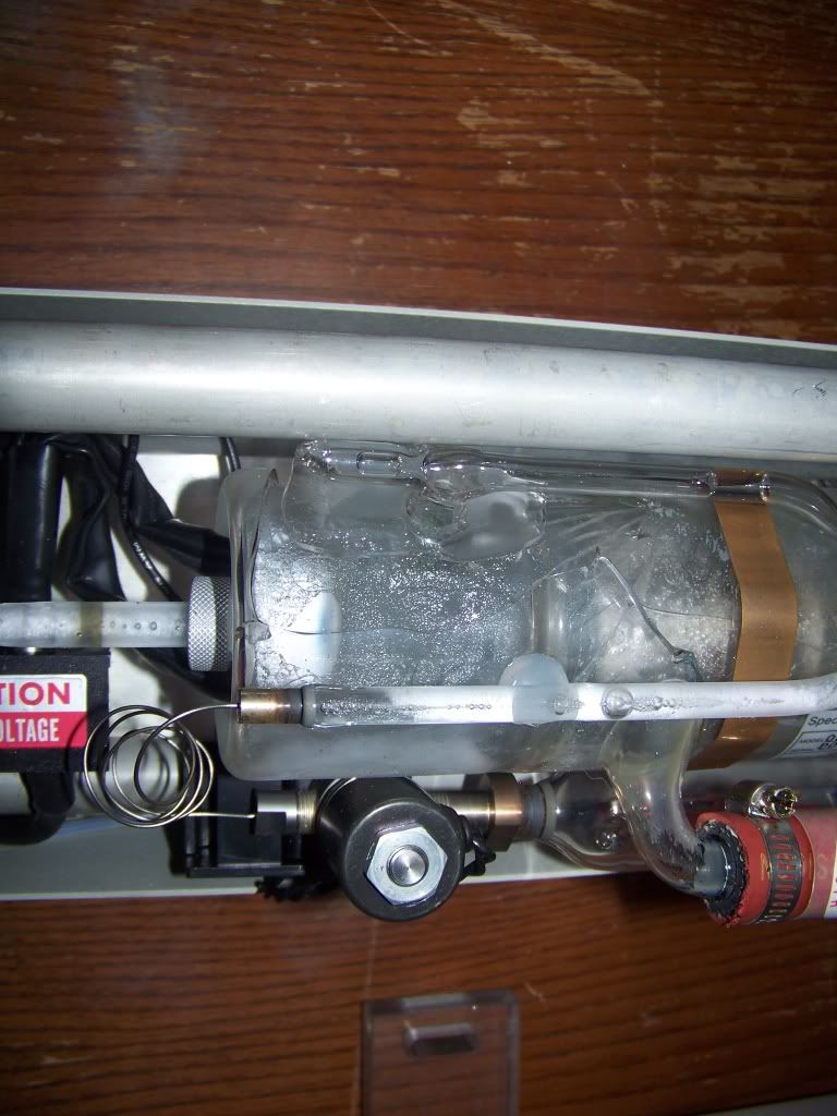
803Tallpinrepair01.jpg

3) using flux or flux cored solder create a blob of solder that bridges to the case of the LD.
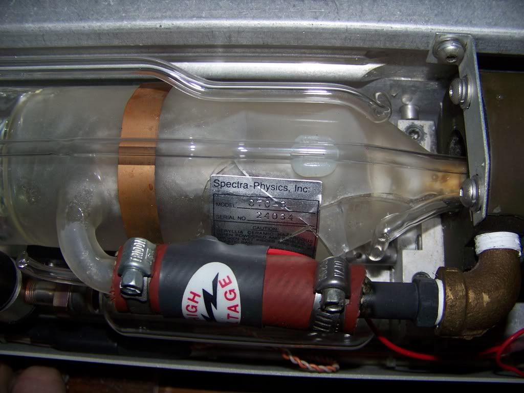
803Tallpinrepair02.jpg

4) Using a piece of stiff copper, single strand, wire bent in a loop (my picture shows a short loop, you could make a long one with the insulation still on). Tin both ends and attach one end to the solder blob...Negative pin sorted...
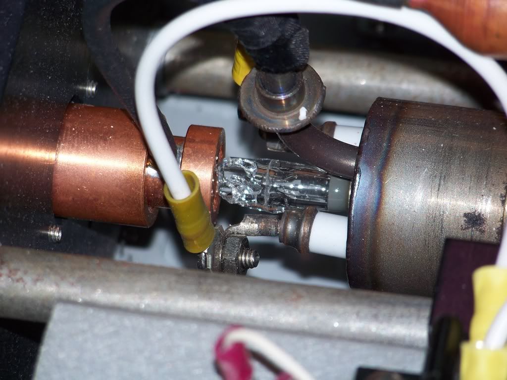
803Tallpinrepair03.jpg

5) If using a short loop clip a bulldog/crocodile clip to the loop to act as a heat soak, then bend the wire until it is centred on the positive pin stub and carefully try to solder the other end of the wire to it, last time I did it it took me about 6 or 7 attempts, the laser still works over a year later.
[edit]once you are happy with the soldering, snip the loop to get the + & - connections you require to go to the drive circuit. [/edit]
You will, not be able to solder this straight onto the Rkcstr driver as it will come apart with the heat when trying to connect it up. Cut the loop and use a clamp again to soak away heat, solder the leads to the driver board.

Hope that helps.

Regards rog8811
[edit]my drawings show LD out of Aixiz module, being in a module makes it easier to hold ;)[/edit]
 
With all due respect, SH*T HAPPENS! i just got into this hobby and have less posts on this forum to even begin to criticize a 500+ post member, yet alone post a link; But your blowing this WAY out of proportion. it's one ~$15 LD, it's not that bad.

i bought numerous of 803T sleds and broke 4 out of 6 LD's that i bought just trying to get those darn LD's out of their heat sinks!
Ruined 2 Rkcstr drivers because of my impatience and frustration. ($100+, Gone...) Yeah i was pissed... but i learned from em'

again, i say all this with the upmost respect. I'm sorry that you experienced some problems, but you have to take it and learn from it, and if this just isn't you hobby, well at least you can say you tired. Trust me, i know how you feel.

Don't take it personally, just trying to help you out. :)
 
Check out everyone's encouragement. But, by the sounds of it you may have already crossed over to the dark side, the side with NO LASERS. That's cool, but perhaps you should just GTFO! ;D

I don't mean to sound cruel, but if it helps you move on, then accept my words above. But in my heart I say listen to my words in the previous page of this thread, along with everyone else who's trying to help you over this hump. Here's a quick fact. MOST PEOPLE SCREW UP THEIR 1ST DIY LASER. I'd say over 80% do SOMETHING wrong. But most of those people take it as a learning curve, and move on. If lasers aren't truly in your heart as they are to the rest of us, then perhaps you're right, and you should move on, you should spend your money more "wisely". I'm not sure what you do for a living, but for a misley PHR for $15 is NOT EXPENSIVE, nor is it an expensive lesson. I paid $60 for my first PS3 diodes that wouldn't give me more then 15mW! But if you keep resisting the Laser Gods, then you won't find further luck in this world and you should just get out. :'(
 
I've killed a few 300 dollar diodes...

I currently have lasers worth thousands that got broken and are now useless.

Shit happens, you'll build one again and it will work.

This might make you feel better:

000_1068.jpg


000_1072.jpg


000_0859.jpg


That's over $1000 (my cost) in broken lasers. Around $5000 surplus cost, and well over $100,000 brand new cost. All broken :D
 
If i broke a 300 dollar diode I would be done, And I have considered getting rid of all my lasers because I really enjoy my vision. If i was blind I wouldn't be able to play video games like i do now =).

It was really a big let down because I knew what i was doing and i still managed to mess up because of human error. That just doesn't sit well with me when I do something unintentional that pisses me off.

@rog I just want to connect it normally like how the pins work because my host is mostly plastic.
 
@rog I just want to connect it normally like how the pins work because my host is mostly plastic

The same basic idea applies, it just means you cannot connect the LD dirrectly to the Rkcstr board as the heat from soldering will undo all your good work. I woulld also suggest that once you do it and check that it works (possitive thinking) encapsulate the back of the LD with epoxy adhesive.

The way I do it is with the Aixiz assembled with the wires sticking out I run the glue down the wires, through the hole in the module. As this sticks the wires together/to the Aixiz and covers the back of the ld, it makes it nice and robust (I don't mean fill the back of the module with glue by the way ;))

Regards rog8811
 
So what do i do with the positive pin, am I just trying to make a loop from the neg to pos holes?
 
The idea of the loop is that as one end is fixed it is easier to position the other end in exactly the right place for soldering. once you have got both ends soldered you snip the loop and you will have the two input wires that you will need to connect it all up to the driver.
(I have edited the post ;))
Regards rog8811
 
ah i see, i'll have to try this out later.  I think the copper wire i have may be too thick would solder wire work as a back up plan?

*EDIT* Both the copper and the solder are just too thick to fit in the pin holes, they can fit like on them but then both would be grounded to the case?


Back
Top