Welcome to Laser Pointer Forums - discuss green laser pointers, blue laser pointers, and all types of lasers

LPF Donation via Stripe | LPF Donation - Other Methods

Links below open in new window

ArcticMyst Security by Avery

Water cooled 3W 445nm Laser

xchg

0
Joined
Aug 7, 2014
Messages
25
Points
3
This is build log for the water cooling module for 3W 445 nm Blue Laser ( NDB 7875 ), to allow laser run at 2.4A for extended amount of time. Practically you can use any kind of laser diode in the standard AIXIS style 12mm module, current will be limited by capacity of FlexMod

Original article - Water cooling 3W Blue Laser - Mobile Modding
Youtube video - https://www.youtube.com/watch?v=gNFzMOxweI8


What you need:

  • NDB 7875 445nm blue laser in 12mm host with G2 or 3 element glass lens.
  • shitty Evercool WC-202 with one extra NB/Videocard water block,
  • Flexmod P3 Laser Driver
  • 2x DC-DC switching converters, 3A
  • 1x DC-DC switching converters, 5A for Laser Driver
  • 3D printed parts, STL files provided
  • 3pin 80mm 12V fan

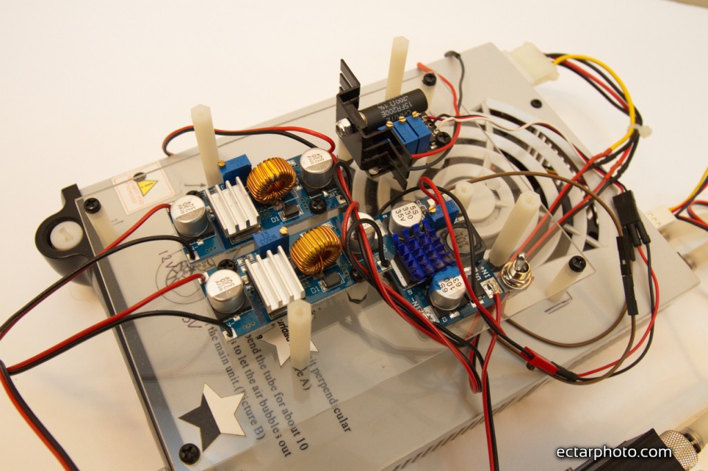
All 4 DC converters are mounted on acrylic base under the fan, fan connected to one of the ports on Evercool and intended to cool down primarily Flexmod driver. Also have 12V, 5V, 8V dedicated DC-DC converters, 8V is for laser driver and has to be 5A capable. 5V and 12V is for the Evercool module.

7D__8932-1024x682.jpg


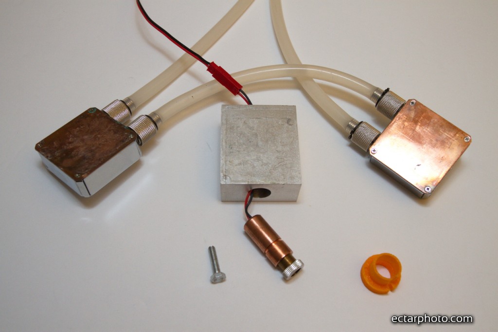
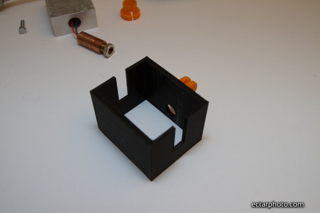
Cooling head consist of 2 video card cooling blocks on both sides of aluminium housing. Housing has 12mm hole for Laser host, and 4mm through hole for the wires.
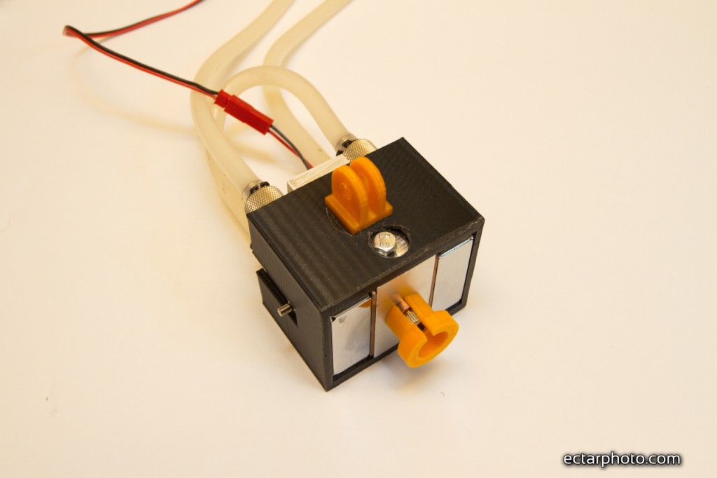
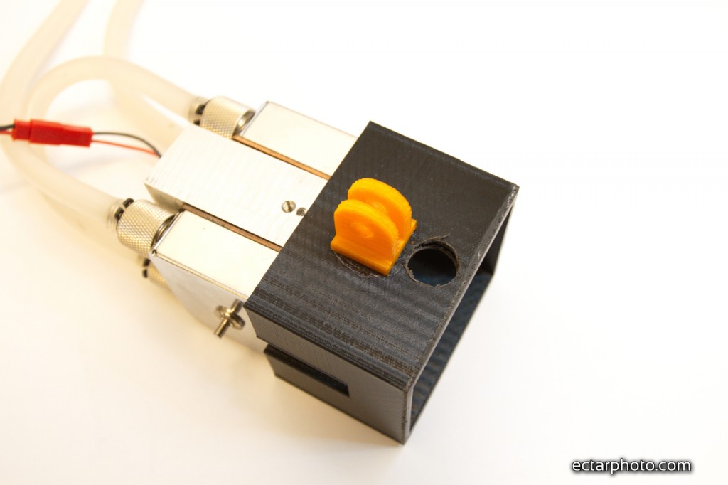
All placed inside 3d printed hosing, which keeps everything nicely pressed together. There should be thermal compound applied between waterblocks and housing, also between laser host and housing.

7D__8919-1024x682.jpg


7D__8925-1024x682.jpg


7D__8921-1024x682.jpg


7D__8920-1024x682.jpg


Evercool module requires 5V and 12V to operate, output connected to the standard PC Molex plug.

7D__8931-1024x682.jpg


Evercool water cooling module has control which suppose to display temperature ( thermocouple supplied but I broke mine ) hence using thermistors. Knob to control speed of the fans. There is a radiator and fan inside the unit as well as water pump and water reservoir. Evercool module monitors RPM of the fans and pump and beeps when one of the unit in not rotating. Here is the look inside:

7D__8936-1024x682.jpg


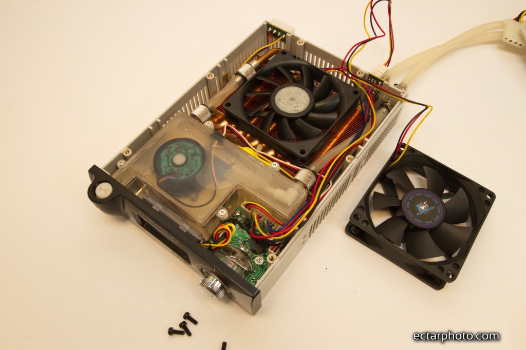
It looks a bit cheesy but it works ok.

In my experiments it was able to keep temperature of the laser 22C and temperature of FlexMod driver 28C after 4 minutes of continuous run.

Any ides and improvements are welcomed. My next idea is to replace radiator with TEC module and run everything in 5-10C Range also replace aluminium housing with copper as I might get galvanic effect between Cu Water blocks and AL housing and degrade both.
 
Last edited:


Joined
Jun 24, 2010
Messages
159
Points
0
I use water cooling in all my projector projects. In some, I will interface a TEC between the laser diode housing and the water cooling block in order to super cool the laser diode to well below zero. This is most useful with the red diodes because the wavelength shift (0.25nm/degree) and the increase in efficiency (1%/degree) will greatly increase the apparent brightness.

You can probably simplify your design in a number of ways. The water cooling blocks will probably work nearly as well if you use only one as the heat you are carrying away is actually quite small.

There is really no need to regulate the fans or the pump. The water is acting to transfer the heat to the atmosphere and will never cool the diode below room temperature. The fans and pump should always remain on and if so then the fan that is inside the small enclosure could also act to cool the Flexmod and this will make the unit more compact.

Thermal interface is an important part of an efficient set up. Grease helps, but the quality of the surfaces is more important. Your cooling blocks and your diode housing should be honed as flat as possible. The way that works best for me is to use several progressively finer grits of sandpaper placed on a flat surface. Drag the mating surfaces back and forth while randomly shifting your grip on the edges as well as rotating the part. You should attempt to get to at least as fine as 600 grit and 1000 is a usual goal for me. You know you are doing well when you place the parts in contact and it takes some pull to separate them due to the nearly vacuum tight interface. At that point you can almost dispense with the grease because the actual contact area is becoming significant (use the grease anyway).

Any ides and improvements are welcomed. My next idea is to replace radiator with TEC module and run everything in 5-10C Range

https://www.youtube.com/watch?v=g9z5ioZhNjE

Some of my videos might give you some ideas. The issue you will face if you decide to begin using TECs is condensation. The housing I show here is easy to construct and works well.
 

xchg

0
Joined
Aug 7, 2014
Messages
25
Points
3
https://www.youtube.com/watch?v=g9z5ioZhNjE
Some of my videos might give you some ideas. The issue you will face if you decide to begin using TECs is condensation. The housing I show here is easy to construct and works well.

Thank you for suggestions, major issue is to have good interference between laser host and waterblock, In my case I do have some play between 12mm host and aluminium body, so I believe there will be the worst thermal interface in whole setup. I have to come up with good solution to this. May be just screw in laser host into waterblock or do thermal press fit or may be use solder (use copper instead of AL)
 
Joined
Jun 24, 2010
Messages
159
Points
0
There is a neat clamping technique that might help. Make a new aluminum block and drill and tap a small hole from face to face near one edge and 1/2 way from the front to the back. Now, carefully drill the 12 mm hole as you did before. Finally, take a saw and cut the block parallel to this 12mm hole through the side with the small hole until the saw has completely split the one side of the block. A screw can then be used to draw the edges of the saw cut towards each other and this will reduce the diameter of the 12mm hole around the 12mm laser cylinder. The smaller the clearance before the cut is made the better the final contact will be when the screw is tightened. This works very well.
 

SyKo

0
Joined
Nov 27, 2013
Messages
204
Points
28
Why must such a interesting build log be ruined by spammers....

This is why we cant have nice things!!

edit: and i used my 100th post to complain about spammers -_-
 
Last edited:

xchg

0
Joined
Aug 7, 2014
Messages
25
Points
3
There is a neat clamping technique that might help....This works very well.

This is great idea, I think I might try this.
There is something I have in my head as well - to do hot fit, heat up AL housing a lot (~400-500C) - it should expand and jam copper laser host in hole quickly hoping it will stay there dead when housing cool down.


Thank you guys for support! I have some more ideas :)
 
Last edited:
Joined
Jul 19, 2016
Messages
1
Points
0
Planters,

I notice your below post while search for information on DIY Liquid Cooling for LED Projectors. I own a Christie Matrix STIM LED projector which was designed for Simulation but I'm using it for Home Theater duty and it throws the best picture I've seen on my screen to date but is very loud so I've been searching the internet to see if I could find a Liquid cooling solution which I cold retro fit to my LED light module. The Matrix STIM is a module projection system and the light engine can be detached from the DMD housing with the removal of 4 screws. The light module uses Luminus Devices PhlatLight PT-120 LEDs. The mounting of the LEDs is pretty straight forward.

Below is a link so you can see what the Christie Matrix STIM looks like:

https://www.christiedigital.com/en-...ojectors/matrix-StIM-DLP-Simulation-Projector


My problem is that I haven't been able to find a Liquid Cooling solution with three water blocks that are small enough to attach to the back of the PT-120 LEDs. I also need to come up with a way to attach them to the actual LED back because of how the LEDs are mounted to the Optical part of the light housing. Do you have a source that can provide such a liquid cooling system or do you piece together your own solutions.

This is my first post but I hope you will respond because I really want to get some ideas about mounting, cost, and level of complication.

Please Respond:angel:

Fraza44


I use water cooling in all my projector projects. In some, I will interface a TEC between the laser diode housing and the water cooling block in order to super cool the laser diode to well below zero. This is most useful with the red diodes because the wavelength shift (0.25nm/degree) and the increase in efficiency (1%/degree) will greatly increase the apparent brightness.

You can probably simplify your design in a number of ways. The water cooling blocks will probably work nearly as well if you use only one as the heat you are carrying away is actually quite small.

There is really no need to regulate the fans or the pump. The water is acting to transfer the heat to the atmosphere and will never cool the diode below room temperature. The fans and pump should always remain on and if so then the fan that is inside the small enclosure could also act to cool the Flexmod and this will make the unit more compact.

Thermal interface is an important part of an efficient set up. Grease helps, but the quality of the surfaces is more important. Your cooling blocks and your diode housing should be honed as flat as possible. The way that works best for me is to use several progressively finer grits of sandpaper placed on a flat surface. Drag the mating surfaces back and forth while randomly shifting your grip on the edges as well as rotating the part. You should attempt to get to at least as fine as 600 grit and 1000 is a usual goal for me. You know you are doing well when you place the parts in contact and it takes some pull to separate them due to the nearly vacuum tight interface. At that point you can almost dispense with the grease because the actual contact area is becoming significant (use the grease anyway).


https://www.youtube.com/watch?v=g9z5ioZhNjE

Some of my videos might give you some ideas. The issue you will face if you decide to begin using TECs is condensation. The housing I show here is easy to construct and works well.
 

plag

0
Joined
Sep 10, 2014
Messages
36
Points
0
Wow! Why won't you get ~10 W with such effective cooling?
The set looks very neat!
 

diachi

0
Joined
Feb 22, 2008
Messages
9,700
Points
113
Wow! Why won't you get ~10 W with such effective cooling?
The set looks very neat!


The diode isn't capable of 10W - even with the best cooling there is. Likely more of an optical limit than anything.
 

plag

0
Joined
Sep 10, 2014
Messages
36
Points
0
The diode isn't capable of 10W - even with the best cooling there is. Likely more of an optical limit than anything.

You could probably use another 445nm diod with higher output in this solid setup.


Top