Welcome to Laser Pointer Forums - discuss green laser pointers, blue laser pointers, and all types of lasers

Buy Site Supporter Role (remove some ads) | LPF Donations

Links below open in new window

FrozenGate by Avery

Using a DC/DC converter to power the laser

IgorT said:
[quote author=chimo link=1194375801/120#124 date=1203094834]I think I may have to pick up some to play with.  Looks like a versatile little chip.

That's great. If more of us play with it, one should get it right sooner or later..

I mean, i'll try my best, but my bet is on you two... :) Then i'll just try to replicate the results.


On the other hand, the 3410 has a circuit in the datasheet, that is pretty much perfect for driving a LD from a single cell Li-Po (Design example 6).. All it needs is two 4.7uH inductors. It's the circuit i posted a page or two ago.

Since almost all the requirements match, i'll just use the recommended parts and hope for the best.[/quote]

Did you find any in a SOT23 package or are they just available in the LLP?


chimo said:
[quote author=phenol link=1194375801/120#121 date=1203086907]Cant wait for LM3410 to arrive...

Thanks for the LM3410 heads up/link. I think I may have to pick up some to play with. Looks like a versatile little chip.[/quote]

he he. your welcome. it was a good find. national shipped a few to me today but they only give samples in LLP. so thats going to be fun to put together
 
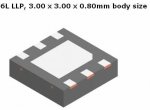
3.00 x 3.00 x 0.80mm body size  :o you could inhale that. but ive seen worse. i just dont know how im going to heatsink it unless it's mounted on a dedicated PCB with copper pour under the chip...
 
chimo said:
Did you find any in a SOT23 package or are they just available in the LLP?
No. The only thing they offer as samples is the XSD (1.6MHz) and YSD(525kHz)  LLP package.

Actually, now that i'm looking at their page again, LLP seems to be the only kind available at all, even tho the datasheet shows two other package types. I don't get it. The other two types available are XSDX and YSDY, again both LLP. Even if you try ordering, the SOT23 package is not available.


phenol said:
3.00 x 3.00 x 0.80mm body size  :o you could inhale that. but ive seen worse. i just dont know how im going to heatsink it unless it's mounted on a dedicated PCB with copper pour under the chip...
You're right. I'll try not to breathe, when i get them. I just got the shipping confirmation for this one too.


Hmm, that center square is GND and also meant for cooling, right?

I think i have some adaptors for that from Conrad. If not, i'll make my own. The IC seems too good, not to be used somehow.
 

Attachments

  • LM3410_package.jpg
    LM3410_package.jpg
    7.9 KB · Views: 125
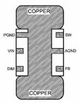
The center pad is meant for cooling. It should be connected to ground plane and thermally coupled to the bottm layer ground plane with vias. the datasheet has some layout and heat dissipation examples. im going to quickly put together a small pcb, draw the traces by hand and etch it in HNO3. making metallized home-brew vias is impossible here, so im just going to leave some copper pour running under the chip, put thermal grease on it and solder the chip on top. Since this may be inadequate to keep it cool, im also going to glue a tiny Al heatsink on the opposite /plastic/ side. if this proves inadequate too, i will have to obtain a professionally made PCB with metallized vias.
 
This is the PCB layout for the LM3410, with the grounded copper cooling pad.


In my country PCB production is extremely cheap. 100€ (144$) is the minimum order, but it would fit hundreds if not thousands of complete 3410 PCBs..
 

Attachments

  • DogBone_layout_for_3410.jpg
    DogBone_layout_for_3410.jpg
    22.5 KB · Views: 99
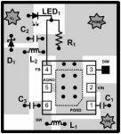
In this picture it looks incredibly simple.
 

Attachments

  • LM3410_PCB.jpg
    LM3410_PCB.jpg
    14.5 KB · Views: 127
phenol said:
if this proves inadequate too, i will have to obtain a professionally made PCB with metallized vias.
As i just mentioned, if i had a gerber file for the PCB layout, i could have hundreds of them done for 100€.. (approx 144$)

If enough of us were interested, this would get VERY cheap.


I always use this company, and they are very good and reliable. They electronically test each PCB on the entire board.. And i don't think you can get it cheaper anywhere...

I would gladly pay for half of it, if a few more people would chip in, it could be done in a week, after the gerber file is ready.
 
thats a lot of power supplies!
i am only worried how to solder the damn thing by hand. i mean how do you heat up under the chip and all the pins at the same time?
 
woop, it should be ok if u only solder AGND and PGND leads and somehow thermally couple the metal pad to PCB copper foil underneath. soldering is also possible with low-temp solder alloys, but.....
 
You could also put a couple of vias under the chip, pre-tin and fill with solder and then heat from the bottom. Not pretty but it can work. You could also mount it "dead bug" style (legs up), put a copper strap across the top and solder it to the board.

woop said:
thats a lot of power supplies!
i am only worried how to solder the damn thing by hand. i mean how do you heat up under the chip and all the pins at the same time?
 
yeah... or use a toaster oven for reflow solder?
maybe use a blow torch (seriously) and some low temp solder paste or something
why do we use moltern metal to stick electronic stuff together anyway? ::)
well i ordered 3 to mess around with. probably should have gotten more
 
In this picture it looks incredibly simple.
LM3410_PCB.jpg

If that chip is a 3x3mm LLP, how are the other components going to fit on there? The space for L1 is in the order of 1 x 0.5mm, i doubt any usable inductors come that small.

As for soldering these kind of chips: I know people do it at home using (low-melting) solder paste and an oven. The major problem with these is keeping them in place as you have to solder the bottom contact too. IC's that dont require thermal contact can be fixed in place with glue.
 
the switching freq is 1.6MHz and inductors have lower value/size respectively. even so, you are right, the allocated space looks insufficient. as regards solderin the thermal pad, i would just leave it unsoldered and put some thermal paste for good thermal contact and only solder the signal pads...somehow.
 
You could, but the 'somehow' would probably still require a paste-and-oven or similar technique. It's undoable to mount these packages onto a pcb with a soldering iron, especially if you want them to be flush with the board surface (for thermal contact).

For something to solder yourself, i'd only consider packages that at least have leads, not pads. Things like SOIC or even TSOP are still hand solderable (though the latter are hard), but with these padded packages it's difficult to even get some solder to properly sick to the pads - let alone mount it.


Back
Top