Welcome to Laser Pointer Forums - discuss green laser pointers, blue laser pointers, and all types of lasers

Buy Site Supporter Role (remove some ads) | LPF Donations

Links below open in new window

FrozenGate by Avery

Using a DC/DC converter to power the laser

woop said:
I have had a bit more luck in ordering samples than you guys. i think i told coilcraft i was a student. anyway i got 6 of the 4.7uH ones and 2 100uH inductors on the way
and i got national to send some samples of the LM3410 but i had to pay shipping
I wonder, if i could still convince them, i'm a student... :)
Did you have to give them information about your faculty and your proffesor, like they say on the page?


Well, i tried explaining what my company does, and hope i get an answer tomorrow.. Otherwise, i tried ordering some inductors from them, and while they are cheap, they simply don't offer a normal shipping method.. The shipping prices started at 122$ and the lowest was 44$.. I don't understand, why they can't offer normal shipping... The same way they use for sending samples would be perfectly fine...

If i can't convince them to give me samples or at least offer normal shipping, i will make another sample order as a student, but to my friend in another city, so they don't get suspicious...


woop said:
so you guys have inductance meters or are you just winging it to wind your own inductors?
I don't have such a meter, and Conrad doesn't carry them, but i saw them on the net for around $60US..

But i do have some ferrite cores, with known AL values, so i used a formula, to calculate the number of windings needed. N = sqr(L/AL) Didn't help much..

In another case, i had a 22uH coil, and when i was trying to pull it out of that cardboard they are glued in, it's enclosure came off. Since it's resistance was too high, i took the wire off, and counted the turns, and wound a thicker wire on it with the same number of turns, hoping it would work. Well, it did work a bit better, but not much..

In pretty much all cases, the voltage increased to 5V quite fast (the better the inductor, the faster), but as soon as i wanted to pull some real current out of it, the voltage dropped miserably... You can connect pretty much anything as the inductor, and get the voltage the IC is set to out on the other side, but once you need it to actually have some power, everything becomes weird..


It really must be a black art, like Chimo said.. :)


IgorT, capacitor type does matter when filtering high-freq ripple. I use a 100uF electrolytic and a 100uF tantalum in parallel. Adding the tantalum made a great improvement in ripple suppression. The higher the load current, the higher the ripple. In a step-up configuration boosting 3V to 6V and Iout=1.1A, with the electrolytic one alone ripple was >1Vp-p. Adding the tantalum reduced it 5-fold. Of course in SMPS also parasitic loops formed by long  and improperly routed traces always make things go south in that regard.
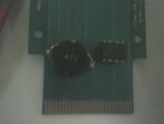
I bought from a local electronics shop a bunch of cheap 47uH inductors which worked well for peak switching current up to about 2A. Anywhere higher than that efficiency dropped rapidly.
The LM3402 switching frequency is 1.6MHz, which is considerably higher than the 50kHz of MC34063. Lower sw freqs reduce conduction losses in transistors and diodes, but require larger inductors.
 

Attachments

  • 47u.jpg
    47u.jpg
    7.9 KB · Views: 174
phenol said:
I bought from a local electronics shop a bunch of cheap 47uH inductors which worked well for peak switching current up to about 2A. Anywhere higher than that efficiency dropped rapidly.
That looks like a proper power inductor.. If i ask for inductors in electronic stores here in my country, they give me the ones, that look like resistors..
When i ask for power inductors, they look at me, like i was crazy or something..


phenol said:
The LM3402 switching frequency is 1.6MHz, which is considerably higher than the 50kHz of MC34063. Lower sw freqs reduce conduction losses in transistors and diodes, but require larger inductors.
I just got a mail saying that national shipped the 3402, so I'm gonna build it and see what happens.

Does that also mean, that a lower frequency IC would be better for free hand soldering jobs?
 
i placed my order on National's web site yesterday morning but the ship date fields still say 'not confirmed'. how long did it take them to confirm?
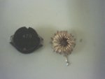
as of inductors, the black one is most efficient with load current < 0.6A (~75-77%)...but the ring works better for higher load currents (~72%).
Axial coils /like resistors/ tend to generate strong fields around them, because their axis is open. Toroidal cores, on the other hand, are closed and the magnetic field lines are confined within the core. Ideally they emit much less EMI and shielding is not necessary.
When tehre is switching going on, the rate at which the current increases/decreases is also an important factor, not only frequency. irrespective of the switching frequency, when designing a SMPS board one should take account of the rise/fall times of the current being switched and the parasitic loops that appear, which means in practical terms that the board design should follow high frequency board design rules in order to avoid such loops.
heres a brief description of the parasitic loops that appear in typical SMPS configurations:
http://www.analog.com/library/analogDialogue/archives/41-06/ground_bounce.html
 

Attachments

  • LL.jpg
    LL.jpg
    8.1 KB · Views: 222
phenol said:
i placed my order on National's web site yesterday morning but the ship date fields still say 'not confirmed'. how long did it take them to confirm?

Wait, let me check my e-mail...

LM3402 Order Verification:    11.02.2008 21:06
LM3402 Order Confirmation: 13.02.2008 13:18
LM3402 Order has shipped:   15.02.2008 6:12

LM3410XSD Order Verification:   14.02. 2008 13:50
LM3410XSD Order Confirmation: 14.02.2008 14:18   <-  This one was very quick.
No shipping confirmation yet.

LM3410YSD Order Verification:   14.02. 2008 13:50
LM3410YSD Order Confirmation: 15.02. 2008 13:28
No shipping confirmation yet.


So it varies.. How long are you waiting by now? Did you get "confirmation", or only "verification"?


BTW: While On Semiconductor doesn't want to ship the samples for free, i found two other manufacturers of the MC34063..
I'm currently trying to order samples from Texas Instruments. Hope it works this time.
 
phenol said:
Axial coils /like resistors/ tend to generate strong fields around them, because their axis is open.
Not to mention the fact, that they are useless for such applications, since they have a very high resistance and a low current rating..
I actually tried them, and while the output did go to 5V, the current was hardly worth mentioning.

I also tried soldering 4 of them in parallel (i was desperate, i didn't have anything else to try), to decrease the resistance and increase the current capability, and it did actually work, but they probably interfered with each other, so again, the increase in efficiency was minor.


phenol said:
Toroidal cores, on the other hand, are closed and the magnetic field lines are confined within the core. Ideally they emit much less EMI and shielding is not necessary.
I have several toroidal cores, but i don't know their AL value, so i tried guessing the turns i would need... Didn't really work very well, one way or the other..

Could you please tell me the diameter and width of your toroidal cores, and the windings that you used, so i could try replicating your results? Also, what diameter wire did you use?
Is there any way to know the AL value at least approximatelly from their size?


phenol said:
heres a brief description of the parasitic loops that appear in typical SMPS configurations:
http://www.analog.com/library/analogDialogue/archives/41-06/ground_bounce.html
Again, thanks Phenol, your information and help are very welcome.

I just hope i'll understand the link you gave me.

Even tho i own a company, that developes custom made electronic devices, i only organize everything - how they're supposed to look, what they are going to do, the user interface and the programming of uPs... Also, when an electronic engineer tells me it's impossible, i bounce crazy ideas off of them, untill they figure it out and admitt it is possible.

While i can build pretty much anything, as long as i have a diagram, i'm lost, when it comes to designing something by myself.. But i'm trying to learn...

So i'm very greatefull for all the help!
 
i just got all 5 confirmations at once on my email...so ive been waiting for roughly 28hours since order placement. The ship dates of all 5 items are still being processed...
the cheapest MC34063 i could find in BG is $0.16 for >5pcs. Anyway, I think that this chip is already old and can be replaced with much better products. Cant wait for LM3410 to arrive...
 
phenol said:
i just got all 5 confirmations at once on my email...so ive been waiting for roughly 28hours since order placement. The ship dates of all 5 items are still being processed...
the cheapest MC34063 i could find in BG is $0.16 for >5pcs. Anyway, I think that this chip is already old and can be replaced with much better products. Cant wait for LM3410 to arrive...

Yeah, me too..

So you ordered five different ICs? What were the other ones?
 
LMH6703MF, LMH6611MKE, LMH6624MF, LMV221SD
high speed op amps and a log HF detector. nobody beats Analog Devices in this field, though 8-)
 
phenol said:
Cant wait for LM3410 to arrive...

Thanks for the LM3410 heads up/link. I think I may have to pick up some to play with. Looks like a versatile little chip.
 
I have several toroidal cores, but i don't know their AL value, so i tried guessing the turns i would need... Didn't really work very well, one way or the other..

Could you please tell me the diameter and width of your toroidal cores, and the windings that you used, so i could try replicating your results? Also, what diameter wire did you use?
Is there any way to know the AL value at least approximatelly from their size?
the AL value depends on the core material. you cant tell what it is by just measuring its physical dimensions. it can be calculated, though, using a test winding on the core and a RLC meter. the best thing to do is look up cores: http://www.kaschke.de/english/framesets/frame_ringkerne.html
all toroids i have /other than the high frequency ones that i use for other purposes/ came from a broken PC power supply. i ahve no idea what their AL parameter is, thats why I wound as many windings as the core could accommodate with 0.8mm enameled copper wire. if your rings allow it, you could use thicker wire to minimize resistive losses.
i dont know what filter caps you use, but i strongly recommed that you find tantalum 100uF capacitors. also, what diode do you have?
 
phenol said:
i dont know what filter caps you use, but  i strongly recommed that you find tantalum 100uF capacitors. also, what diode do you have?

I did find many tantalums, when you told me to look for voltage regulators in my old DVD burners. So i'll replace all with those. I very conveniently found pretty much all the values i need.. :)

You mean the diode in the MAX circuit? Don't remember right now, but it's exactly the one recommended in the datasheet.
 
chimo said:
I think I may have to pick up some to play with.  Looks like a versatile little chip.

That's great. If more of us play with it, one should get it right sooner or later..

I mean, i'll try my best, but my bet is on you two... :) Then i'll just try to replicate the results.


On the other hand, the 3410 has a circuit in the datasheet, that is pretty much perfect for driving a LD from a single cell Li-Po (Design example 6).. All it needs is two 4.7uH inductors. It's the circuit i posted a page or two ago.

Since almost all the requirements match, i'll just use the recommended parts and hope for the best.


Back
Top