Welcome to Laser Pointer Forums - discuss green laser pointers, blue laser pointers, and all types of lasers

LPF Donation via Stripe | LPF Donation - Other Methods

Links below open in new window

ArcticMyst Security by Avery

Unusual 532nm-module from Aries-type host

Krutz

0
Joined
Nov 21, 2007
Messages
1,733
Points
48
impressive! what output was advertised? i would put this module in a bigger host..
and whoa, thats a huge doubler crystal! if its around 100mw from this, i would consider doing some blue experiments too :)
with 700mA i get 100mW green from my o-like module too. a totally different world, compared to your module. so much potential, 100mW green is almost an insult for this! :)

dave has a blue crystal set from a burned out pointer, by the way.. ;-)
..and there was a blue crystal set on ebay, someday..

manuel


Joined
Dec 26, 2007
Messages
682
Points
28
I have rewired the TEC-driver to it's original configuration, (heating the KTP, cooling the module-body).

I am having trouble reducing the current to the TEC. It seams to read .5A, or it drops to nothing, if the pot is turned "down". It is almost like the driver only switches on or off, in response to the feedback-sensor, but always at .5A, like a thermostat.

I would really love to build a 473nM in this guy, seams more worth it than the green. I would need a 2W+ IR-pump too. I am guessing this one is 1.25W like the rest of the Aries. New emitter-driver would likely be needed too, this one is likely going to max-out at a little over an Amp.

Does anyone know if I would need to replace the KTP also, not sure about the AR-coating being specific for 532nM. It would be perfect if I only need to replace the primary-crystal, in the optical-train anyway.

Thanks for all of the help guys :)

Barry
 
Joined
Apr 30, 2008
Messages
104
Points
0
You would need to swap the ktp with an LBO or KN crystal in order to double the fainter 946nm line. It's unknown at this time just how efficient the 946 line is of that particular nd:yvo4 crystal, but it's definately worth the try. You don't need to change the primary crystal, unless it is too small and you want a more powerful pump diode(as you mentioned), or you want more then 2-10mW of blue.
 
Last edited:

Krutz

0
Joined
Nov 21, 2007
Messages
1,733
Points
48
from what i understand you have to change *any* optical component! both crystals (and lenses, if they belong to the actual cavity, if there are any, which i doubt). The output-lens ("telescope") can stay.
the other crystals need to be coated optimized for 946/473nm *and* suppress the much stronger 1064/532 line. you should either look for a "set" of crystals, or try to get a broken blue pointer.
for the pump diode: that wouldnt necessarily help (from 1.25 to 2w). if the emitter size is much larger, the power density falls, and you end up with much more pump light not used. if the emitter size is double the width, for example. well, just have a look what it states, if you buy one :)

for an improvised setup for driving the pumpdiode, you may use several AMC7135 chips. parallel a few, you will get stable 300mA for each. i run my greenie with two of these, nothing else, and wirks fine.

manuel
 
Joined
Dec 26, 2007
Messages
682
Points
28
Excellent info, thanks. I was afraid it wouldn't be quite as easy as changing a single crystal.

There is a lens for focusing the C-mount-FAC-output onto the primary-crystal, maybe that would allow a little more pump-light in from a larger C-mount? I have experimented with 473nM a little already, and I could only get 7mW from 1.2W of 808nM, doesn't even begin to lase until about 1W of 808-pump. It would be nice to get the 473-output up to 20mW or so. This color is so nice :)

BTW,
I don't know the advertised output of this original system, I do not even know who made it. I bought it from the LG-garage sale, (thanks again Scopeguy!), but it must have been an experiment or sample, as it is not a product they sell.

Barry


from what i understand you have to change *any* optical component! both crystals (and lenses, if they belong to the actual cavity, if there are any, which i doubt). The output-lens ("telescope") can stay.
the other crystals need to be coated optimized for 946/473nm *and* suppress the much stronger 1064/532 line. you should either look for a "set" of crystals, or try to get a broken blue pointer.
for the pump diode: that wouldnt necessarily help (from 1.25 to 2w). if the emitter size is much larger, the power density falls, and you end up with much more pump light not used. if the emitter size is double the width, for example. well, just have a look what it states, if you buy one :)

for an improvised setup for driving the pumpdiode, you may use several AMC7135 chips. parallel a few, you will get stable 300mA for each. i run my greenie with two of these, nothing else, and wirks fine.

manuel
 

HIMNL9

0
Joined
May 26, 2009
Messages
5,318
Points
0
Uhm, wait, please ..... you said it was becoming hot very quickly ..... the TEC and crystal holder, i suppose, right ?

And not stabilizing on a certain temperature ?

If yes, for logic, it was connected in reverse ..... i mean, if the TEC and the thermal sensor was there for heat the crystal, it must heat it until a certain temperature, then stop and keep it at that temp ..... if instead the temp was rising quick and not stopping at a certain point, it was a mistake ..... try to follow my line of think ..... if the TEC was connected in reverse, it was expected to cool the crystal, so more the temp increase, more the driver was pumping current in the TEC, and if was in reverse, this mean more heat ..... avalanche effect in few seconds .....

Or i'm wrong ?

I suppose you don't have tried if the temperature stabilize at a certain level, right ?
 
Joined
Dec 26, 2007
Messages
682
Points
28
Your thinking is very valid, but I think it was meant to warm the cyrstal from the beginning now.

Now that I have a better understanding of the design-intention, I think the driver for the TEC just needs to be adjusted-down, so it swicthes off the current to the TEC at a lower-temp. I still need a better understanding of the drivers operation, but this seams to be the case. The pot on the driver does not seem to adjust the current, like our LD-drivers, instead it adjusts when the driver supplies current to the TEC, it is always delivering .5A to the TEC, when it is on.

Uhm, wait, please ..... you said it was becoming hot very quickly ..... the TEC and crystal holder, i suppose, right ?

And not stabilizing on a certain temperature ?

If yes, for logic, it was connected in reverse ..... i mean, if the TEC and the thermal sensor was there for heat the crystal, it must heat it until a certain temperature, then stop and keep it at that temp ..... if instead the temp was rising quick and not stopping at a certain point, it was a mistake ..... try to follow my line of think ..... if the TEC was connected in reverse, it was expected to cool the crystal, so more the temp increase, more the driver was pumping current in the TEC, and if was in reverse, this mean more heat ..... avalanche effect in few seconds .....

Or i'm wrong ?

I suppose you don't have tried if the temperature stabilize at a certain level, right ?
 
Joined
Nov 7, 2008
Messages
5,725
Points
0
You would need to swap the ktp with an LBO or KN crystal in order to double the fainter 946nm line. It's unknown at this time just how efficient the 946 line is of that particular nd:yvo4 crystal, but it's definately worth the try. You don't need to change the primary crystal, unless it is too small and you want a more powerful pump diode(as you mentioned), or you want more then 2-10mW of blue.

The 946nm line in Nd:YVO4 is quite weak. Normally when using Nd:YVO4 to generate blue you go for 457nm since the 914nm line is quite strong in comparison.

To generate 473nm, Nd:YAG is the laser crystal of choice and it is usually used with LBO or KNBO3. The Nd:YAG must be coated for 946nm and the LBO for 473nm.
 

HIMNL9

0
Joined
May 26, 2009
Messages
5,318
Points
0
The pot on the driver does not seem to adjust the current, like our LD-drivers, instead it adjusts when the driver supplies current to the TEC, it is always delivering .5A to the TEC, when it is on.

Well, is easy to see, if the driver is still working correctly, ofcourse ..... if it heat the assembly until a certain temp, then stop, or also just reduce, the current for keep that temp, then is working correctly.

Unfortunately, the TEC plates are very critic in current eating, in a short range of voltages, so sometimes is difficult to make measures on them ..... i mean, after all, all the TEC plate is basically a serie of diode junctions, so, until the minimum voltage, no current, and when the minimum voltage is reached, a little voltage variation cause a big current variation ..... a possible way for try to measure if it's working good, or if the driver is in short circuit and just continuously feed the TEC, is to put a 0,1 ohm, 3 or 5 Watt resistor in serie of it, and then measure the voltage on it, same as for the dummy load for the LD drivers (you just need a more low and powered resistor :p)

Ofcourse, with the TEC and the sensor assembled :p

If when you turn it on, you see a certain amount of voltage, then at a certain temperature it go down, then it work right ..... if instead the TEC feeding remain at the same value also when the assembly is heated, there's something wrong, in the driver or in the regulation.
 
Joined
Dec 26, 2007
Messages
682
Points
28
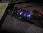
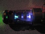
I have not had much time to play with this module much latley, I did take a couple interesting pictures of while running, you can see the IR pretty well. Thought it may be interesting.

I have decided that the LD-driver is not functioning properly, gets very hot, quickly and begins to drop it's current output within 30-seconds.

I think I will give up on the idea of a 473nM set-up for this, probably better to build that completely from scratch. I will see how much 532 this baby can crank out once the driver is fixed,... maybe a new 2W diode too ;)

-DH
 

Attachments

  • IMG_3413 (Medium).JPG
    IMG_3413 (Medium).JPG
    64 KB · Views: 138
  • IMG_3414 (Medium).JPG
    IMG_3414 (Medium).JPG
    52.3 KB · Views: 127
Joined
Nov 7, 2008
Messages
5,725
Points
0
Are you intending to keep it portable? If you would be willing to make that module into a lab-style system, you could drive it with a flexmod from drlava and have analog modulation as well if you ever felt like making a projector..


Top