Welcome to Laser Pointer Forums - discuss green laser pointers, blue laser pointers, and all types of lasers

Buy Site Supporter Role (remove some ads) | LPF Donations

Links below open in new window

FrozenGate by Avery

Status of Cheap DIY Laser Power Meters?

Upon reconsideration many of the nonlinear regression methods are probably overkill and intended for more complex problems.  I am leaning more towards treating the numbers as an infinite series.

The sum of an infinite series is given by:
a / (1 - r)
Where a is the first term and r is the ratio between terms (r < 1).

Create a series using the differences between successive values and its sum will be the difference between the oldest value and the asymptote.

Ex:
Original Data:
2, 3, 3.5, 3.75

Differences:
1, 0.5, 0.25

a = 1, r = 0.5, sum = 2.

The series will converge at sum + initial value or 2 + 2 = 4.

You will of course have to average the ratios between each term and probably keep a floating average of the final values to make everything nice and smooth.  I would also skip the math if r < 0.1 or something, negative ratios may start doing bad things.

I can always code up a sample function in Java or something.


IMO refine the sensor a bit, stick it all in a box with a PIC and LCD and you have a winner. If you program it to self-calibrate with a 5 minute cycle or something and can make them for 30-40$ accuracy in the +-10% would be fine.


Bionic-Badger said:
Seoguy, you seem to have everything figured out.  Coherent, Newport, Ophir and all these companies have just been rooking professionals and hobbiests alike with their overpriced technology that any chump on a laser hobbiest board could replicate.  

But talk and optimism is cheap.  So, why don't you put your money where your mouth is and bring about this grand DIY revolution in laser power meters.  After all, according to your calculations, they should be cheap, easy to manufacture, calibrate, and distribute.  I'm sure you'll get rich doing it, but maybe those laser-meter companies will send their shaven gorillas to prevent you from exposing their ruse.

LMFAO..... ;D ;D ;D ;D ;D.....ROFL.... ;D ;D ;D

Jerry
 
691175002 said:
Create a series using the differences between successive values and its sum will be the difference between the oldest value and the asymptote.

Ex:
Original Data:
2, 3, 3.5, 3.75

Differences:
1, 0.5, 0.25

a = 1, r = 0.5, sum = 2.

The series will converge at sum + initial value or 2 + 2 = 4.

I can always code up a sample function in Java or something..

Could you provide an example of going from those readings to the result of '4'?

I dont mind java, c or pseudocode - whatever you like.
 
Benm said:
[quote author=691175002 link=1234443192/32#32 date=1235179113]
Create a series using the differences between successive values and its sum will be the difference between the oldest value and the asymptote.

Ex:
[highlight]Original Data:[/highlight]
2, 3, 3.5, 3.75

Differences:
1, 0.5, 0.25

a = 1, r = 0.5, [highlight]sum = 2.[/highlight]

The series will converge at sum + initial value or 2 + 2 = 4.

I can always code up a sample function in Java or something..

Could you provide an example of going from those readings to the result of '4'?

I dont mind java, c or pseudocode - whatever you like.
[/quote]
Hey Benm....
from the "Original Data"... take the first entry = 2
then add the "sum" = 2 which is 2 + 2 = 4. 8-)

Jerry
 
Here is probbably the code you want:
Code:
    public static double seriesSum(double a, double b, double c, double d) {
      // Find Differences
      double da = b - a;
      double db = c - b;
      double dc = d - c;
      
      // Find Ratio
      double ratio = (db / da + dc / db) / 2.0;
      
      if (ratio < 0.1)
         return d;
      
      // Find Final Value
      return a + da / (1.0 - ratio);
   }

If you just combine the formulas you end up with this, no idea if it could be simplified:
Code:
final = a + (b - a) / (1.0 - ((c - b) / (b - a) + (d - c) / (c - b)) / 2.0);

Here is the full source including comments and test cases.  It also contains a longer function that will perform the same operation on any number of elements.
Code:
public class Sum {

   /**
    * @param args
    */
   public static void main(String[] args) {
      System.out.println (seriesSum (new double[]{3,3.5,3.75,3.875}));
      System.out.println();
      System.out.println (seriesSum (new double[]{5.1,7,8.2, 8.8, 9.2}));
      System.out.println();
      System.out.println();
      
      System.out.println (seriesSum (3,3.5,3.75,3.875));
      System.out.println();
      System.out.println (seriesSum (20,27,33,35));
   }
   
   /**
    * Find the asymptote of a set of data that converges on a specific value.
    * This is a general function that will work on any number of values.
    * @param data  Array of samples, requires at least three.
    * @return
    */
   public static double seriesSum(double[] data) {
      if (data.length < 3)
         return 0;
      
      System.out.print ("Data: " );
      printArray(data);
      
      // Create a new array that contains the differences between each element of the original.
      double[] differences = new double[data.length-1];
      for (int i = 0; i < differences.length; i++) {
         differences[i] = data[i + 1] - data[i];
      }
      
      System.out.print ("Differences: " );
      printArray(differences);
      
      // The final value in this series will be first_term / (1 - ratio)
      // ratio = term / previous term.
      
      //Find the average ratio
      double ratio = 0;
      for (int i = 1; i < differences.length; i++) {
         ratio += differences[i] / differences[i-1];
      }
      ratio /= differences.length - 1;
      System.out.println ("Ratio: " + ratio);
      
      // If the ratio is very small the chances are that the math is just going to make the results worse:
      if (ratio < 0.1)
         return data[data.length - 1];
      
      // Otherwise do some math
      return data[0] + (differences[0] / (1 - ratio));
   }
   
   /**
    * This would be more suited for a micocontroller.
    * @param a
    * @param b
    * @param c
    * @param d
    * @return
    */
   public static double seriesSum(double a, double b, double c, double d) {
      // Find Differences
      double da = b - a;
      double db = c - b;
      double dc = d - c;
      
      // Find Ratio
      double ratio = (db / da + dc / db) / 2.0;
      
      if (ratio < 0.1)
         return d;
      
      // Find Final Value
      return a + da / (1.0 - ratio);
   }
   
   public static void printArray(double[] array) {
      for (int i = 0; i < array.length; i++) {
         System.out.print(Math.round(array[i]*1000.0)/1000.0 + ", ");
      }
      System.out.println();
   }

}
Sample output:
Code:
Data: 3.0, 3.5, 3.75, 3.875, 
Differences: 0.5, 0.25, 0.125, 
Ratio: 0.5
4.0

Data: 5.1, 7.0, 8.2, 8.8, 9.2, 
Differences: 1.9, 1.2, 0.6, 0.4, 
Ratio: 0.5994152046783616
9.843065693430646


4.0

37.294117647058826

EDIT: I should also mention that this function will only work for rising data, for falling data one would have to compare the first and last values and if they are decending, change the + da / (1-ratio) to -da / (1-ratio).
Also I should have enforced that the ratio < 1. If the ratio is greater than one bad things start happening.
 
Thanks - very interesting stuff!

The full code doesnt seem feasible in the processor and language i'm using (i doubt it does arrays at all), but the example for 3 values i'll try. Perhaps it would work better with 4 or 5, we will see.

Working with rising and falling series should be fixable.. but i wonder what happens if neither the endpoint nor the startpoint of the series are zero - for example, a slow transition from a reading of 100 to 150.
 
I've done a little simulation on this method of calculation... as i expected, it works perfectly well from theoretical numbers, but noise on input data is a huge problem.

I've included a couple of charts with variable amounts of noise (all converge to value 8). Results seem usable with noise levels lower than 1000 ppm* of the measured signal, but at 1% it's totally shot.

Dealing with a 10 bit DAC and about 1% noise (from a average-64 sample!), i see trouble ;)

* the middle chart has 1200 ppm noise - a median of 10 datapoints works well for getting a decent prediction.
 

Attachments

  • noise.jpg
    noise.jpg
    205.2 KB · Views: 152
lasersbee said:
[quote author=Bionic-Badger link=1234443192/16#28 date=1235175172]Seoguy, you seem to have everything figured out.  Coherent, Newport, Ophir and all these companies have just been rooking professionals and hobbiests alike with their overpriced technology that any chump on a laser hobbiest board could replicate.  

But talk and optimism is cheap.  So, why don't you put your money where your mouth is and bring about this grand DIY revolution in laser power meters.  After all, according to your calculations, they should be cheap, easy to manufacture, calibrate, and distribute.  I'm sure you'll get rich doing it, but maybe those laser-meter companies will send their shaven gorillas to prevent you from exposing their ruse.

LMFAO..... ;D ;D ;D ;D ;D.....ROFL.... ;D ;D ;D

Jerry[/quote]
Gee Jerry, what's so funny ::) I think it's utterly HILARIOUS ::)
 
daugin, I think you may be misconstruing my intentions on this thread. Unlike some here, I am NOT a commercial venture or trying to sell my wares, I am a private hobbyist.

"Naysayers" have value too. They usually point out the major challenges to be overcome.

That kind of "constructive criticism" is quite valuable, for instance, Benm's first post pointed-out some of the issues that need to be overcome, for which I am very grateful. But there is a difference between "constructive criticism", and someone who hits you with a long barrage of negative comments and insults, with the clear intent of discouraging you (and the rest of the forum members) from even pursuing the project at all and promoting somebody's product instead.

you will need to do some work...before others will spend their time trying to help you.

daugin, I am new to both this hobby and this forum, so please forgive me if I may have more questions than answers on some topics at this point. But I think that you will see that I am making an effort to contribute here as best as I am able. :)
 
lasersbee,

1) He indicated that your meters were the equivalent to a DIY project...

Laserbee's meter is about as close as you're going to get to a DIY-class meter...

I figured he was basing that claim on the fact that some of your products are sold without a case. I was merely pointing-out the differences between a TRUE DIY project, done for the benefit of the group...

such as what knimrod did here -
http://www.laserpointerforums.com/forums/YaBB.pl?num=1200112201
and here -
http://www.laserpointerforums.com/forums/YaBB.pl?num=1203305181
or that Benm did here -
http://www.laserpointerforums.com/forums/YaBB.pl?num=1225820689/16
and here -
http://www.laserpointerforums.com/forums/YaBB.pl?num=1226965719
and andrea87 helped with here -
http://i40.tinypic.com/21j7lm8.png

vs. a commercial product like yours.

2) I was basing that on the linked pricing information YOU provided me here, which lists your LaserBee I meters at ~$210 & ~$290. I had not come across that meter or price on eBay.

But looking at that listing now, his claim of a $150 meter is still incorrect. The starting bid is ~$160, the actual listed purchase price (buy now) is ~$170. The listed shipping price to the US also seems a little high for something that small, does it really costs more just to ship this than the entire price of those surpl. heads? Or is this that old eBay trick of shifting part of the purchase price into the shipping cost to make an auction appear less expensive?

In any event, I'm glad you brought this to my attention, because it raises a very important question in my mind...

Why were you trying to charge me (and other forum members here) substantially more $$$ than you charge any old Joe on eBay???! >:( >:( >:(

Thanks for the forum discount, there, buddy! :(

3)

"Benm"... actually...needed to have...
... so you're a little off there

All I said there was I thought his unique auto-calibration capability was a great idea. While I would agree that whether it can be fine-tuned to provide greater accuracy is still an open question, in principle, the concept of having an on-board reference source would mitigate the need for external calibration.

And to be sure that your DIY theories, circuits and calculations are giving you the correct
output... you WILL need a calibrated LPM... no mater how you slice it...

Not necessarily, and even then, perhaps only to validate the initial design.

And if using a pre-calibrated sensor, and depending on the complexity of the design, all that may be required is a reference laser to make sure that the meter was working as expected.

May I also observe that rather than thinking of solutions to these issues, you seem bound and determined to deride any approach that does not involve purchasing a meter calibrated against a professional LPM? ::)

4)

So basically... you are saying...

No, I did NOT say that. You are misquoting me, and taking my quote out of content, just to reshape it to your own ends.

What I said was that I thought it was ridiculous to claim that the people in this forum were too impatient, unskilled or stupid to be able to build such a DIY project.

If you disagree and think that they ARE, let me know. But don't cut a few words away from the statement they were referencing, just so that you can distort my comments to the opposite of what I actually meant.

the New Thermopile Technology.....
Show us.. that new non-archaic Thermopile Technology...

I will be addressing that question in a more relevant post shortly.
 
If you are willing to share J.BAUER Electronics LaserBee I research and development costs we will
be more than happy to share our Schematics, Parts Lists, PCB...

I never asked you for all that stuff, see my post above. I only asked you one very specific question, which you have somehow managed to avoid answering TWICE now.

I guess I missed that question....

That's what I figured, you just must have missed it, and assumed as much when I politely brought it to your attention here a second time -

That reminds me, I asked you a question in a previous post in this thread, but you must have missed it, as you never gave us a reply -

Quote:
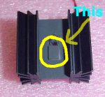
"By the way, that heat sink/sensor pic in the thermal-based meter you linked to is an excellent example of the kind of quality DIY head I was talking about! What make/model thermopile device is that using?"

Here is the pic I was referring to -
http://www.bauer-electron.com/ebypics/dlb01.jpg

Thanks!

I must confess that I did find it a bit odd, given the post in which that question first appeared was a dedicated response to you, replying specifically to issues you had raised in your two prior posts to me.

A post that you had read, replied to, and even quoted from.

Even stranger, that quote came from the exact same small section of that post as that question.

Strangest of all, the part you quoted was only FOUR SENTENCES AWAY from the question you didn't see!

But I figured that if my assumption was correct and you somehow:question missed seeing it, and were not instead evading answering the question, that all I had to do was bring it to your attention again, and an answer would be forthcoming!

as to the picture of the "archaic sensor"... the same Thermo-couple technology is being
used today on Lab Quality Thermopile heads... that cost so much..

lasersbee, you must feel very conflicted, to be arguing so strenuously that more advanced devices do not exist, when you know for yourself that that is not true.

I cannot help but laugh over the idea that that archaic, bulky, low junction count, bimetal device, manufactured during the fall of Saigon, when John Lennon releases "Rock & Roll", Tiger Woods was born, the Bee Gees were #1, and Sony introduces the brand new, state-of-the-art "Betamax", represents the pinnacle of technology!

Or that while technological advancements in every other field advanced by leaps and bounds, advancements in thermal sensing technology somehow got "frozen in time", like a bad re-run of "life on Mars", for the past 30 years!

you keep harping on the New Thermopile Technology...

OK, I'll give you an example...

Show us.. that new non-archaic Thermopile Technology that is being used by companies like Coherent or Newport...or any other commercial LPM manufacturer...

I was looking into advanced thermopile devices in general, not just those used by companies like Coherent, as from what people have posted here, it sounded like some of them have "fallen behind the curve" technology-wise. But if you want to limit it to only devices being used in commercial LPMs, OK.

I'm willing and eager to learn about and see this new technology as others here are as well...

I am very glad that you agree with me of the importance and value to the group of learning about these.

So ready to see an example of a more modern, lighter, smaller, more advanced device?

(drum roll, please...)

.
.
.
.
.
.
.
.
.
.
.
.
.
.
.
.
.
.
.
.
.
.

Here it is -
 

Attachments

  • Modern1.jpg
    Modern1.jpg
    53.7 KB · Views: 152
;D ;D ;D ;D ;D ;D ;D ;D ;D ;D ;D ;D ;D ;D ;D ;D ;D ;D ;D ;D ;D ;D ;D

And here I was thinking that you didn't have a sense of humor

Peace,
dave
 
lasersbee, now that you have openly agreed with me on the importance and value to the group of learning about more modern devices that can be used for LPMs, assuming you practice what you preach, can you please finally answer for us all the question I posed to you 2 pages ago...

By the way, that heat sink/sensor pic in the thermal-based meter you linked to is an excellent example of the kind of quality DIY head I was talking about! What make/model thermopile device is that using?

Thank you!
 
I'm looking forward to seeing any refinements you are able to make!

Thank you, Benm!

I think the best improvements i can make to it are mostly digital

I may not know much about lasers yet, but computers is something I can help you with!

One of the things that you have to remember when designing, is that hardware and software are often interchangeable! 8-)

using a microcontroller to improve response and such, but that would make it more difficult to reconstruct...

Agreed. But consider this - why do we have to go to the complexity of putting all the smarts on-board?

Next thing i'll try is to use a pic16f877's builtin a/d converters to sample the signal, but i'm not sure it'll work well yet
.....

I'm not sure if that will be necessary. I think one of the reasons that knimrod went with that PIC on his i/f board was that it gave him an easy way to serialize the data and i/f with an RS-232 port.

I'm not sure that we will need to do that in this case.

Measuring such low voltage (differences) with 10 bit resolution has its noise problems

Don't forget that link I posted above to the guy selling the LTC1050 Precision Zero-Drift Operational Amplifiers on eBay for $2.50, the same ones that were being used to solve a similar problem? ;)

And on the flurry of math you and 691175002 having flying back and forth, I am quite impressed with your efforts to "predict the future"! (calculate the endpoint of the curve)

But might I suggest that rather than go to that level of effort and complexity to, as I understand your explanation, compensate for a response time deficiency in the current sensor design, why not first explore improvements in the sensor to eliminate the deficiency to begin with? 8-)

Many of those improvements I had been giving a lot of thought to were related to sensor design, so I hate to see you go to all of that effort and added design complexity to post-compensate for a problem that we end up fixing? ;)
 
I'll work out the noise, I think that what may be happening in the later charts is that the 4 values are too close together so its hard to get an accurate ratio, if you only worked with every second datapoint you may get more accurate results.


Back
Top