Welcome to Laser Pointer Forums - discuss green laser pointers, blue laser pointers, and all types of lasers

LPF Donation via Stripe | LPF Donation - Other Methods

Links below open in new window

ArcticMyst Security by Avery

Starting a new project on a Spectra-Physics 163-CO207 / 263-CO6 - pretty pics and learnings so far

bd1323

New member
Joined
May 1, 2021
Messages
17
Points
3
Hi there,

This is my first thread past my intro post, just wanted to share some of what I have learned playing around with an argon toy I picked up. This is also my first home laser project - so I welcome any constructive criticism or suggestions! (as to the standard safety warnings, my professional background is in med device regulatory quality and safety and design verification testing including 21CFR1001-1050 and 60601-x, but if you see anything unsafe I will be very thankful if pointed out!)

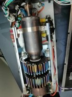
So I was starting to tinker around again to occupy myself and had been growing more and more interested in optics and lasers, and saw this gem on e-Bay and based on the cord alone couldn't resist.
0.jpgtubesmall.jpg

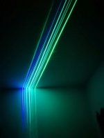
With the help of the amazing and generous work of Sam for creating and making freely available the wealth of info on Sam's Laser FAQ I breadboarded up a quick controller (and very slowly cobbled together bunch of single pin connectors to deal with the substantially over specified 37 pin AMP connector used for the REMOTE interface....) and slapped a couple multimeters on to monitor current and status and was quite happy with the result (though not my photo skills trying to get a shot of spectral divergence)!


IMG_20210501_145706small.jpgIMG_20210501_145525small.jpgargon.jpg

There were a few differences noted between the feedback being received and the input amplitude drive voltage vs. what was listed on SAMs (both ^) picked up a NI USB-6009 to get better control and monitoring over it (those things are great and cheap on ebay) and am planning on trying to acquire or build a proper light meter (if I can figure out a way to calibrate it) and probing around a little more to try and capture responses from built in feedback vs. direct measurement and better characterize everything. The supply doesn't seem to be regulating quite right, (tube current seems to climb and indicates unregulated) and that may be contributing to the difference, but once I know more and if there is interest I will post an update with fun graphs of things. I also will be making a proper controller, there are quite a few threads on that aspect but if anyone is interested will include updates on that also. Also just ordered some monochromator parts and a photomultiplier tube...because well...anyway...With work travel updates not be super frequent.

thanks for looking and have fun!
-Brandon
 
Last edited:


Joined
Jan 2, 2008
Messages
1,513
Points
83
I'm always interested. Nice tube and great work at getting it running on your own without much help.

I love that it has 8 lines, so it should be a fairly healthy tube with good life left in it. Great project to work on, keep it up and let us know how it goes!
 
Joined
Sep 20, 2013
Messages
17,252
Points
113
By "light meter" I expect you mean a laser power meter. They used to be available from many sources, but those have died up except for Laserbee in Canada. The owners name is Jerry and he's a member here. He goes by Lasersbee because Laserbee was already taken.
 
Joined
Jan 2, 2008
Messages
1,513
Points
83
By "light meter" I expect you mean a laser power meter.
That makes more sense now :) I wondered what he meant, but that is not at all what I was thinking he meant.

I was thinking he was talking about the "light" mode of air cooled argons:

"Light/Current switch - selects either current or light mode. Light mode regulates the laser output power. Current mode runs the laser at a constant current."
 
Last edited:

bd1323

New member
Joined
May 1, 2021
Messages
17
Points
3
Time for a little update and a solid demonstration of my inexperience with lasers :) (as to above, the intent was along the lines of a laser power meter to compare to the built-in feedback just for fun, I should have been more specific there -it seemed to always be regulating based on light mode feedback to me, though I could be wrong here) Alsopaul1598419 thank you for the tip, I just ordered a LaserBee USB from Jerry's website!


Now on to the fun stuff and what may be the story of how I quickly destroyed my first (but not last) laser :oops: and some things I found interesting about the behavior along the way to its demise. No idea as to what it may mean, but looked interesting so thought I would share. 🤞it is just a power supply issue...all comments and criticisms welcomed...

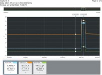
I got back home and I still hadn't moved past a simple breadboard controller, but wanted to play around and see what things looked like when drive voltage went up vs when new lines started to appear and stuff playing around, and captured some of these fun pics and a few runs of what looked like pretty "normal" (coming from a standpoint of no knowledge of what that actually should be) behavior, one example below from idle to max and back that I happened to save didn't show anything that looked out of place to my untrained eye, the large wiggles are me playing with it as I was just turning a pot by hand.

IMG_20210523_004727.jpgIMG_20210523_001930.jpgstable ramp.jpg
Note for all captures: I didn't do a good job capturing this data and was just streaming at max data rate without regard to the time constant , so X-axis intervals should be fairly consistent time slices but I don't know how that is handled here, and I don't know the scaling, and there is a chance I got them out of order.
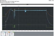
Y-axis scaling (from specs on SAMs - built in feedback) Tube current(orange): 0.1A/V built in light mode feedback (blue): 1mW/1V Applied Drive Voltage(Green where present): 1V/1V

Now I kept playing around with it a little and then left it on idle for a while I was trying to mess with the capture software, when I went back to start looking I noticed this occur along with what was probably my imagination but I thought a sort of orange uncollimated flare in the output reflecting either brighter or that I didn't notice before on the surface of a diffraction grating it was shining on at the time.


ramp1.jpg

So I shut it down and let it cool off and then started trying to investigate in what are probably ridiculous manners and laughter is fair game here- but hey, it's my first laser and i wanted to understand what if anything was up. I tried to recreate the orange glow on the diffraction grating with no success, tried to project an image of the orange by moving a microscope objective around the grating, that was a total fail but made for a neat pic when flipped around. Tried using a phone and goggles to snap a picture inside down the beamline, but I think all that was visible was the filament?. Finally sort of caught a glimpse of the orange portion using a phone and goggles to snap picture through microscope beam splitter and objective lens that was more representative of what I thought I was seeing, here it just looks like a slightly darker orange blur to the right, and maybe nothing all along but who knows and my lack photography skills doesn't help reveal anything new 😁
IMG_20210523_004315.jpg IMG_20210523_170657.jpgIMG_20210523_170119 (2).jpg
This was all at idle, I started to try and capture the issue again a few times and got this type of behavior when prior to this the laser was running comfortably at 55mW with no jittery behavior.

unstable.jpg

For curiosities sake I later zoomed in on the noise and it looked periodic, this is another section where it showed clearer, I did an FFT but without decent time base units all it showed was that there was some central band about which it was oscillating. I will post that and rest of story in a follow up since this is max number of attachments (if that is bad form here - let me know and will avoid in future).unstable periodic zoom.jpg
To be continued in next post...
 

Attachments

  • IMG_20210523_004320.jpg
    IMG_20210523_004320.jpg
    24.7 KB · Views: 1
Last edited:

bd1323

New member
Joined
May 1, 2021
Messages
17
Points
3
Continued from last post to allow attachment of additional data. The FFT of the section above is below (total real time in that capture window is probably around half a second - though time units here aren't known as the data was streaming) and shows that there was indeed some periodicity to it.
FFT of unstable run.png
For comparison, I ran an FFT on an earlier capture at max output levels, captured before I first noticed what looked like odd behavior to me and it didn't show this broad spike:FFT of max output no oscillations.png

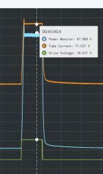
So now the sad part, while the laser was running at idle I noticed it suddenly brighten for a very small fraction of a second and quickly pressed capture and got this (Note the drive voltage ADC input was maxed with this scaling so actual value is unknown, scaling for others is fine to 100V for current and 75V for light feedback mode signal reading on Y-axis scale:
glitch1.jpganomoly.jpg

I though maybe my crappy breadboard had shorted or something crazy like that, but after removing the drive voltage return from the breadboard/pot setup entirely so it was just open between pins other than the ADC across them this started happening:
last glitches.jpg

And a zoomed view of the final glitch details just for fun:


last glitch zoom2.jpg

So after that I shut it down, for what I didn't know may be the last time as it will now no longer lase. The tube does ionize when the starter fires, I couldn't get an image but it is a bright pinkish through orange glasses looking glow that pulses with what I think is the starter trying to fire. Interestingly the light feedback from the laser picks something up, my guess is induced current from the pulse as I never saw any sort of light flash beyond the ionization glow.

Now I am wishing I had had a voltage meter across the tube when it was running poorly to see if the voltage was in the ballpark, from my recollection it was around 85-90V when I had measured before, I don't really want to hook anything up to that while it is trying to constantly start. I plan on investigating the power supply and trying to find a way to safely make sure that it is at least delivering enough current to give the tube a chance and something hasn't failed in it.

So kinda sad I may have managed to destroy my cute little laser so quickly, but hey even if it isn't anything that turns out to be fixable it was fun learning and playing, will make the next try better! (Already broke down and eBayed an Agilent Z4203-60207 HeNe and P/S - I can't be laserless!)

I'm always happy to answer questions and I also welcome any input on whether this type of content is relevant or suggestions to improve future postings, and while I don't want to be seen as begging for help by any means on my first thread and plan on continuing to research, probe around and learn more I wouldn't turn down any advice in that regard either 😊.

Thanks for looking,

-Brandon


Top