Welcome to Laser Pointer Forums - discuss green laser pointers, blue laser pointers, and all types of lasers

LPF Donation via Stripe | LPF Donation - Other Methods

Links below open in new window

ArcticMyst Security by Avery

SSY 1's Recently?


Ulao

0
Joined
Mar 16, 2014
Messages
33
Points
0
This is the set of cheap lenses I've been using for my LIBS system I have used various ones from the set over the last year and have had no problems with them.
5 Piece Loupe Set
The set is 5 lenses, various focal lengths and cheap. I've seen them on sale for $1.99. I bought 3 sets, use them for lots of projects.
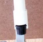
Attached is a bad pic of the lens holder I made for these lenses. Started with 1 1/4 PVC union and cut a groove inside on the lathe then did the cutout you see in the pic. Snap one lens out the other in. Lens holder detail.jpg
 

Ulao

0
Joined
Mar 16, 2014
Messages
33
Points
0
Ulao -- (John) ---
I got the carbon bar stock.
PM me your address and I'll send you a chunk!
HMike

Hey John --- This is my first Pulse sensor I machined from carbon. The dust isn't too bad....
It is 0.924" OD, 0.2275" thick and has a 0.070" thick x0.70" Dia target area. I can thin that down if you
think it would work better.

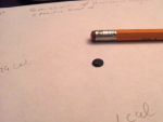
9421-ndyag-sensor-copy.jpg

Let me know how this works. My method was based on the idea that the laser pretty much covers the entire disk and thus deposits the energy evenly on the disk. since the mass of the disk is known and the specific heat and absorption (>98% at 1064 nm) are also known the energy can be calculated from the temperature rise. I am guessing that the rim on your sensor might lead to computational complexities. Not saying it won't work, especially for larger power. I just wouldn't want to have to model that complex geometry. You must know the mass and if it's evenly it's good.

Note how small the sensor is? That's because the amount of radiation is so small it won't heat much carbon. Sensor.png So the smaller you keep the sensor the more sensitive it becomes. My problem was that when I operated over 750 volts the carbon began to ablate. By making the diameter larger that could be avoided but I wouldn't want to increase it more than say 20 or at most 30 percent. Remember that mass would increase as the square of diameter.

Q=C M (delta T)

Where Q = quantity of heat (calories)
C = specific heat of carbon
M= mass of sensor
T = temperature

The more I think about using this type of sensor universally I realize that a sensor like this won't work over a large range of measurements. In other words too much energy would heat the sensor too much and too little energy wouldn't heat it enough. So-- One would have to taylor the sensor to the measurement or taylor the measurement to the sensor. Supplying several different mass sensors would be one solution, varying the amount of time the laser was on would be another.
 

Ulao

0
Joined
Mar 16, 2014
Messages
33
Points
0
"I had read somewhere that the q-switch on the SSY-1 is fragile and can't handle being over driven.. I will have to find where I've read that."

That seems to be the consensus. I'd like to know more about that.
 

Ulao

0
Joined
Mar 16, 2014
Messages
33
Points
0
The q-switch in my sissy-1 looks like a solid crystal. If it is in fact a dye filled chamber then the outside walls are no more than a couple thousandths of an inch thick which would make it very fragile. Chad at MI tells me he routinely removes them by using a punch and tapping on them. I doubt that such a dye filled chamber would stand up to that kind of abuse. What I think (at least mine) is that this q-switch is a Cr4+ doped YAG crystal.
Here are pictures from a couple of manufacturers websites:
cr4+.jpg and passive-q-switch.jpg
Passive Q-Switch - Cr4+YAG - Cr:YAG | Scientific Materials Corporation | Saturable Absorber Passive Q-Switch
And
Cr4+:YAG

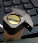
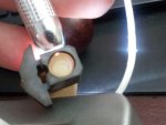
This picture shows that the q-switch essentially fills the cell it's mounted in and the color matches a lightly doped Cr YAG crystal.
Q-switch3.jpg
This picture shows that the walls if any are transparent.
Q-switch2.jpg

An interesting specification for Cr YAG is the damage threshold which is sometimes stated as 500-1000 mw/square centimeter.
density 4.56 g/cubic centimeter -- Dense. No?
Mohs hardness 8.5. It wont be easy to scratch that. Of course it is AR coated.
Thermal conductivity 12.36 W/m/k Not a real good heat conductor.

I feel better about punching my q-switch out of my old flash tube holder to put it in my new one now.

I just bid on a Sissy-2 from Part2go. They are now listed for $140 -150.
The price went up in the last 2 weeks no doubt because of discussions here.
I bid on $140 listing. I bid $110, they counter offered $130, I countered $115, they took it.
 
Joined
Jan 7, 2007
Messages
6,309
Points
83
I'm not sure how to detect Q cell damage. On my -1, the optic path appears clear to my eye looking through it. I don't know if the cell darkens with abuse or just stops working like new. The Q cell on the -1 appears solid as you have noted. Pictures and direct observation of the -2 cell shows a bubble inside and a tiny sealed filling nipple on the side. My -2 which has the Q cell has a piece of tape over a cutout where that filler nipple is positioned -- The other one has no cutout for it.

John -- That carbon sensor is made so there is a small thin area at the center of the target which can be quickly read before the heat dissipates through the carbon or the contacting heat sensor. That larger collar facilitates mounting. I think I will try to machine it down to ~ 0.040" ............
HMike

Sissy-2 LOL !!!!!!

I got it down to 0.035" thick - It's getting fragile!! The final sensor will likely be an instant display - Oscope or similar.
 
Last edited:
Joined
Jan 7, 2007
Messages
6,309
Points
83
I think the spam evaporated !!!! I love
spring time !!!!!
John -- Your package will ship tomorrow --
The carbon just falls on the lathe bed.....

I'm tired of trying to align this -2 laser with that window in there -
I'm getting trash spots all over the place even without the HR mirror assembly.
That window is about to go and this laser will be OC --- ROD --- HR ......
3/24: I'm still getting many dots. I managed to get the brightest dots aligned
and will try a shot tomorrow.
HMike

John, Mike S hasn't posted here yet.
 
Last edited:
Joined
Jan 7, 2007
Messages
6,309
Points
83
John -- I'm switching over to the "factory" PFN I received.
I'm using a tiny photoflash charger and at 4.0 V input, I have 600
VDC on the block -- that's 4.68 Joules. If I add two of those
low ESR caps I removed from the bad module, I'll have 6.5
Joules - near the limit of the tube.
HMike
 
Joined
Aug 14, 2013
Messages
2,655
Points
63
I was running this one at 10.89J, but at only 330V. Maybe you told me where it was these tubes start
coming apart, but I forgot. There isn't a search feature for private messages.
 
Joined
Jan 7, 2007
Messages
6,309
Points
83
LS ---
I believe you are running the SSY-1 --- I'm working on the -2.unit.
You need to look at Sam's info on these. Sam's Laser FAQ - Commercial Solid State Lasers .......
The info there is insane! the original PFN is a 36 mFd Cap using a 30 uH coil.
Some there say 15 Joules should be Max.
HMike
03/26 -- I converted my -2 to use the original PFN. At 560 Vdc -- kinda sick :-(
I added another 10 mFd and it's getting better. These caps are low ESR design
and should provide the short pulse.

03/28: The caps in the original PFN are about 1 x 1.25" for 5 mFd. They are non-polar and appear to be very LOW ESR.
Photo flash caps are electrolytic and have a higher ESR which may be why those small camera flash tubes can take 20 Joules....
It's the higher impedance of those caps I guess. Their internal R makes up for the Impedance of the coil.
I just added 50 mFd of photo caps across the 26 Mfd of the PFN and noted a larger reaction from the carbon target.
We have a lot of experimenting to do here.
 
Last edited:

Ulao

0
Joined
Mar 16, 2014
Messages
33
Points
0
Mike I just received a SSY2 today and I will be trying to fire it up but since you've been there perhaps you will offer some guidance.
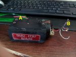
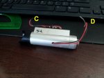
First I've pasted pictures of the laser & the cap assy here with the leads labeled. Would you indicate what is the function of each set of leads?
(My Hebrew is rather rusty)


SSY2-CapAssy.jpg

SSY2-Laser.jpg

What voltage do I apply to the caps?
How do myou trigger it?

Any other wisdom you may have gained too will be appreciated.
 
Joined
Jan 7, 2007
Messages
6,309
Points
83
Ulao ---
First off, these laser heads which come from Israel, are a knock-off of the original SSY-1 heads developed long ago for range finding. I coined the name "SSY-2" for simplicity.
They are very similar but have smaller flash tubes in the cavity which limits power.
You have a lot of questions, so I'll try as time permits to answer them.

First Photo: 1--- Wires A on the PFN are capacitor input from the PS. Read my previous posts about this device with its caps and coil.
Although the caps are Non-polar, keep RED as +. Most results I have read indicate 600 VDC input although the caps are rated at 630 VDC. This will provide about 5 Joules to the tube depending on your PFN.
2 --- Wires B on the end of the PFN are labeled E1 and E2. E1 is the + (RED) output through the PFN coil and it goes to the flash tube (RED).
E2 is the - which is common to the black input wires. Remember that these are very LOW ESR caps and need the impedance of the coil to protect the flash tube. E2 connects to the black flash tube wire.

Can someone translate the label on the side???

More later --- HMike
 
Last edited:


Top