- Joined
- Jan 5, 2024
- Messages
- 151
- Points
- 43
I’ve got a lot of experience in a lot of different fields.. if I had a lathe I would’ve already dropped the NUBB24/28 laser…

Follow along with the video below to see how to install our site as a web app on your home screen.
Note: This feature may not be available in some browsers.


Another discussion side topic, with using my li-po batteries to run drivers for the NUB diode array series of the 445nm blue lasers, I really haven’t seen a Vf increase when pushing. 4-5+ Amps? I have in my possession, NUBM31, NUBM37, NUBM35, NUBM38, NUBB23 and NUBB24 arrays and so far, none of them have had the same increase as we see with the NUBM47, NUBMOF, or Osram 8W diodes? With pushing 5+Amps, you would think you would see 4.4-4.6Vf? For the NUBB24, you would think you when then see the diode array pulling closer to 33-34Vf? But that’s not the case at all, with my experience, with the rise in current, and driving them for 30-40seconds, I see a drop in Vf and then they stabilize around 0.12V lower, they should pull 4V at 3A, but they actually pull less.. I’m not sure if this is happening because I’m running TEC plates and fans for cooling, and I don’t let the temps ever exceed 50-60*C at the heatsink.. I’m going to hook up my NUBB24 setup tonight and post my results pushing 3A, 4A, 5A, and maybe 6A.. with the data sheet info, they appear to be pretty close to the NUBMOF in terms of output.. that would be awesome if they are because pushing them to 5+ A should yield 8W+.. putting the NUBB24 around 60W, and the NUBB28 in the 80W range, and that’s modest, they could easily handle 5.5-6A and yield 8.5-9W per diode.. I wish I had a bigger LPM..
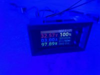
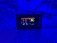
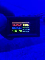
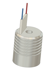
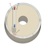
If you read all the way thru, it was the start of milling the slot, the design is supposed to be a fully milled slot about 42mm deep…I am not sure what exactly you are doing with the tec there. It frankly looks like it wont help the thermals at all.
You cant just mill a slot in a solid block of aluminum and put a tec in there, it will just thermally short circuit the tec adding a shit ton of heat load to the heatsink.
If mounted correctly, a 1/2 of a NUBM28 needs a tec with roughly QcMax = 43W just to pump the heat.
if you want any significant temp difference from hot to cold side of the tec - to have the heatsink hotter than the diode - you need much more than that.
Say you want to keep the diode at 20°C while your heatsink is at 50°C. This means 30°C temp difference across the tec while it still pumps 43W.
A !good! TEC1-12706 will just barely do that: pump 43W at 30°C difference while using a whoping 85W to do so. (resulting in an abismal ~0,5 COP)
Thats 14V@6A!
Doing that will result in 43W Pumped + 85W Tec power usage being dissipated into your heatsink.
For a heatsink thats say 0,23K/W you would end up with a heatsink temperature of just around 50°C (at 20°C ambient and 20°C diode temperature).
That same heatsink used without a tec would keep the diode at 30°C while using 85W less power!
So you get 10°C lower diode temperature for huge cost, complexity and and additional 85W of power input and just 1/3 of the runtime using the same batterys.
That imho just makes no sense.
If you don’t use enough TeC plates at the correct current, then yeah, the diode heat will overcome the whole attempt to cool it.. I’ve tested this using NUBM37 diodes, NUBB23/24, and the smaller 7-8W diodes..Years ago many other members try something similar only the used different method since the are more experienced in this field.I also was curious and used similar heatsink like yours and added a cheep Tec and tiny fans i believe the are 5X5 and the problem was one side will heat the heatsink and one side was cooling it so it was a fail, So what i did was i add a Tec right behind the diode and added a heatsink on the Hot end and it worked ok the only problem was the diode failed and was a tiny bit wet or moister build no idea.
farbe2 is not pulling your leg he is correct.
Anyway good luck i keep an eye to see if you’re projects will work
Go ahead and explain a thermal short circuit and how it would occur in my heatsink/TEC setup.. cuz I don’t see how it could even happen, and I believe you’re using incorrect terminology for this concept..Yeah, sure…
I was talking about a thermal short, not a electrical one but you seem to completely miss that.
Maybe you can show the heat load calculations to proof your point?
Take for example the:
The World Leader in Thermal Management Solutions
lairdthermal.com
A high performance tec from a very well known company.
It doesn’t really make sense to me to discus the application if you aren’t willing to learn how to really use tecs and how to calculate all thermal aspects of a system.
Just to let you know, it’s very much possible to just mathematically derive a solution that will show you exactly how a tec will perform, which temperatures you will get at which parts of a assembly and how much power it draws. If you really want, you could even simulate heat flows on your PC without spending time on the mill just to find out it doesn’t work.
Not sure why you are hurt.
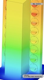
BTW, I do this (every day) for a living, so I am fairly sure I know what I am talking about. Simulation of a multi diode laser module:
View attachment 78399
Didnt i do that in my first post? Just for it to be not read?And if you were talking about a thermal short, then why not just state that?
You cant just mill a slot in a solid block of aluminum and put a tec in there, it will just thermally short circuit the tec adding a shit ton of heat load to the heatsink.
Very informative, thank you!Didnt i do that in my first post? Just for it to be not read?
How it works:
View attachment 78408
The 20x40mm Tec you are using will move heat, it doesn't produce cold. It just moves heat from its cold side to its hot side (reversible by polarization change but that does not matter).
If you power the tec and make the cold side face the bore where the diode sits, it tries to move the heat to the outside but:
The outside and the inside are one piece. The aluminum will just conduct the heat from the outside back into the middle part essentially thermally shorting out the tec.
View attachment 78409
Just like if you try to fill a swimming pool with a pump but the pump is sucking water from the same swimming pool you are trying to fill. The pool will not get fuller!
It also doesn't matter if you use 2 or even three tecs, same concept: trying to fill the pool with multiple pumps all sucking from the pool they are trying to fill.
The right thing to to would be to divide the pool into two sections by using a barrier, that barrier is the insulator between hot and cold side.
With this barrier, and the pumps sucking on one side and pumping to the other, they would be able to produce a water hight (or temperature) difference between both sides: thats what you tec is doing but with no barrier.
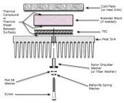
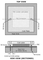
Normally, tecs are clamped between two thermally conductive surfaces with screws and thermally insulating washers that prevent heat from flowing back into the cold surface.
Like this:
View attachment 78410View attachment 78411
One image specifies "SS screws" thats not something German, that stands for stainless steel.. Why? Because it is a very poor thermal conductor, which keeps the "short" to a minimum, a minimum amount of heat flowing back into the cold side. The other drawing specifies Nylon spacers or fiber washers, another type of thermal insulator. (Think about it like the pool: the screws are holes in the pool barrier, having big holes will make the pumps struggle to create a water hight difference because the water will just flow back to the lower side)
Also: your tec is just "slid" right into the slot, there is no mounting pressure at all on the surfaces. Tecs need around 75-200PSI of pressure to work right and dont break over time. The pressure also keeps their thermal resistance between the tec and the mounting surface in check, too low pressure means too high resistance to efficiently remove the heat from the hotside.
The Belleville spring washer sets this pressure and keeps it under different thermal expansion situations.
Ever used a CPU cooler on a CPU without its spring clamps? -> similar concept -> not good
Now to your setup.
I used this tec: https://lairdthermal.com/de/product...peltier-cp-series/CP10-131-04-L1-TOW-W4.5/pdf
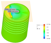
and just run it at a 20 watts of power you will get this: (redder is hotter, bluer is colder, see scale on the right side)
View attachment 78412
You can see the tec in the slot tries its best to create a temp different but only reaches 30,113°C-29,852°C = 0,26°C!
So the core is a whopping 0,26°C colder than the outside while wasting 20W of electrical power.
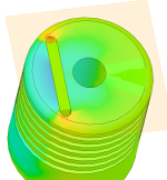
Its even clearer if we look at the heat flow: (redder = more heat flow, blue = less heat flow)
View attachment 78413
You can clearly see the red/orange/yellow areas around the slot ends where the aluminum heatsink connects the two tec sides. The heat flow is the highest there because it's the shortest route between hot and cold side of the tec.
Disclaimer: I just used guessed at the dimensions for the CAD model, the tec is 40x20mm and the bore is 9mm, outside is 35mm, this looked like his pics, but it could be slightly different.
Sure having more power into the tec will result in higher temp differences, but come on, its like using a fire department type pump in a kids sized inflatable pool and saying: "See, I can get the water to splash around a little more, so it must be filling..."
I suggest the following: Try replacing the Tec with an aluminum plate, keep the fan and measure the diode temperature and power again. Temperature will be lower, power higher and battery will last longer!
Just removing the tec might be slightly worse as the tec acts as an essentially perfect thermal conductor in this scenario, so leaving the slot empty would introduce thermal resistance.
Good information, I like that you backed up your argument with proper information- But you’re forgetting that there will be 2 fans and a additional heatsink on the outside of the original heatsink to cool down the hot side.. obviously the efficiency of this design would depend on a few things: slot gap tolerance, (milling it to within 0.001” of the TeC plate thickness should yield the results i planned on) ambient temperatures, and adding a precool/timer function to the TEC plates so they could get a head start on the heat transfer process..Didnt i do that in my first post? Just for it to be not read?
How it works:
View attachment 78408
The 20x40mm Tec you are using will move heat, it doesn't produce cold. It just moves heat from its cold side to its hot side (reversible by polarization change but that does not matter).
If you power the tec and make the cold side face the bore where the diode sits, it tries to move the heat to the outside but:
The outside and the inside are one piece. The aluminum will just conduct the heat from the outside back into the middle part essentially thermally shorting out the tec.
View attachment 78409
Just like if you try to fill a swimming pool with a pump but the pump is sucking water from the same swimming pool you are trying to fill. The pool will not get fuller!
It also doesn't matter if you use 2 or even three tecs, same concept: trying to fill the pool with multiple pumps all sucking from the pool they are trying to fill.
The right thing to to would be to divide the pool into two sections by using a barrier, that barrier is the insulator between hot and cold side.
With this barrier, and the pumps sucking on one side and pumping to the other, they would be able to produce a water hight (or temperature) difference between both sides: thats what you tec is doing but with no barrier.
Normally, tecs are clamped between two thermally conductive surfaces with screws and thermally insulating washers that prevent heat from flowing back into the cold surface.
Like this:
View attachment 78410View attachment 78411
One image specifies "SS screws" thats not something German, that stands for stainless steel.. Why? Because it is a very poor thermal conductor, which keeps the "short" to a minimum, a minimum amount of heat flowing back into the cold side. The other drawing specifies Nylon spacers or fiber washers, another type of thermal insulator. (Think about it like the pool: the screws are holes in the pool barrier, having big holes will make the pumps struggle to create a water hight difference because the water will just flow back to the lower side)
Also: your tec is just "slid" right into the slot, there is no mounting pressure at all on the surfaces. Tecs need around 75-200PSI of pressure to work right and dont break over time. The pressure also keeps their thermal resistance between the tec and the mounting surface in check, too low pressure means too high resistance to efficiently remove the heat from the hotside.
The Belleville spring washer sets this pressure and keeps it under different thermal expansion situations.
Ever used a CPU cooler on a CPU without its spring clamps? -> similar concept -> not good
Now to your setup.
I used this tec: https://lairdthermal.com/de/product...peltier-cp-series/CP10-131-04-L1-TOW-W4.5/pdf
and just run it at a 20 watts of power you will get this: (redder is hotter, bluer is colder, see scale on the right side)
View attachment 78412
You can see the tec in the slot tries its best to create a temp different but only reaches 30,113°C-29,852°C = 0,26°C!
So the core is a whopping 0,26°C colder than the outside while wasting 20W of electrical power.
Its even clearer if we look at the heat flow: (redder = more heat flow, blue = less heat flow)
View attachment 78413
You can clearly see the red/orange/yellow areas around the slot ends where the aluminum heatsink connects the two tec sides. The heat flow is the highest there because it's the shortest route between hot and cold side of the tec.
Disclaimer: I just used guessed at the dimensions for the CAD model, the tec is 40x20mm and the bore is 9mm, outside is 35mm, this looked like his pics, but it could be slightly different.
Sure having more power into the tec will result in higher temp differences, but come on, its like using a fire department type pump in a kids sized inflatable pool and saying: "See, I can get the water to splash around a little more, so it must be filling..."
I suggest the following: Try replacing the Tec with an aluminum plate, keep the fan and measure the diode temperature and power again. Temperature will be lower, power higher and battery will last longer!
Just removing the tec might be slightly worse as the tec acts as an essentially perfect thermal conductor in this scenario, so leaving the slot empty would introduce thermal resistance.
Also, my original plans for this setup was to use the M21G convoy host, which would have a heatsink diameter closer to 45-48mm.Didnt i do that in my first post? Just for it to be not read?
How it works:
View attachment 78408
The 20x40mm Tec you are using will move heat, it doesn't produce cold. It just moves heat from its cold side to its hot side (reversible by polarization change but that does not matter).
If you power the tec and make the cold side face the bore where the diode sits, it tries to move the heat to the outside but:
The outside and the inside are one piece. The aluminum will just conduct the heat from the outside back into the middle part essentially thermally shorting out the tec.
View attachment 78409
Just like if you try to fill a swimming pool with a pump but the pump is sucking water from the same swimming pool you are trying to fill. The pool will not get fuller!
It also doesn't matter if you use 2 or even three tecs, same concept: trying to fill the pool with multiple pumps all sucking from the pool they are trying to fill.
The right thing to to would be to divide the pool into two sections by using a barrier, that barrier is the insulator between hot and cold side.
With this barrier, and the pumps sucking on one side and pumping to the other, they would be able to produce a water hight (or temperature) difference between both sides: thats what you tec is doing but with no barrier.
Normally, tecs are clamped between two thermally conductive surfaces with screws and thermally insulating washers that prevent heat from flowing back into the cold surface.
Like this:
View attachment 78410View attachment 78411
One image specifies "SS screws" thats not something German, that stands for stainless steel.. Why? Because it is a very poor thermal conductor, which keeps the "short" to a minimum, a minimum amount of heat flowing back into the cold side. The other drawing specifies Nylon spacers or fiber washers, another type of thermal insulator. (Think about it like the pool: the screws are holes in the pool barrier, having big holes will make the pumps struggle to create a water hight difference because the water will just flow back to the lower side)
Also: your tec is just "slid" right into the slot, there is no mounting pressure at all on the surfaces. Tecs need around 75-200PSI of pressure to work right and dont break over time. The pressure also keeps their thermal resistance between the tec and the mounting surface in check, too low pressure means too high resistance to efficiently remove the heat from the hotside.
The Belleville spring washer sets this pressure and keeps it under different thermal expansion situations.
Ever used a CPU cooler on a CPU without its spring clamps? -> similar concept -> not good
Now to your setup.
I used this tec: https://lairdthermal.com/de/product...peltier-cp-series/CP10-131-04-L1-TOW-W4.5/pdf
and just run it at a 20 watts of power you will get this: (redder is hotter, bluer is colder, see scale on the right side)
View attachment 78412
You can see the tec in the slot tries its best to create a temp different but only reaches 30,113°C-29,852°C = 0,26°C!
So the core is a whopping 0,26°C colder than the outside while wasting 20W of electrical power.
Its even clearer if we look at the heat flow: (redder = more heat flow, blue = less heat flow)
View attachment 78413
You can clearly see the red/orange/yellow areas around the slot ends where the aluminum heatsink connects the two tec sides. The heat flow is the highest there because it's the shortest route between hot and cold side of the tec.
Disclaimer: I just used guessed at the dimensions for the CAD model, the tec is 40x20mm and the bore is 9mm, outside is 35mm, this looked like his pics, but it could be slightly different.
Sure having more power into the tec will result in higher temp differences, but come on, its like using a fire department type pump in a kids sized inflatable pool and saying: "See, I can get the water to splash around a little more, so it must be filling..."
I suggest the following: Try replacing the Tec with an aluminum plate, keep the fan and measure the diode temperature and power again. Temperature will be lower, power higher and battery will last longer!
Just removing the tec might be slightly worse as the tec acts as an essentially perfect thermal conductor in this scenario, so leaving the slot empty would introduce thermal resistance.
Oh my god, this guy...But you’re forgetting that there will be 2 fans and a additional heatsink on the outside of the original heatsink to cool down the hot side..

