Welcome to Laser Pointer Forums - discuss green laser pointers, blue laser pointers, and all types of lasers

Buy Site Supporter Role (remove some ads) | LPF Donations

Links below open in new window

ArcticMyst Security by Avery | Browser Hide by Avery

Some new design ideas w/TEC plates and High Speed fans…

using those tiny batteries wouldn’t be ideal, the small mAh rating would be drain extremely fast, and the output would drop off fast.. they really need a lot of capacity, I would say it’s more important than having higher voltage.. I’ve seen this issue with my dual fan 8w M21A laser.. I run 2-Vapcell M11-v1.0 batteries in series and the output drops off fast, not from heat, but simply from the capacity dropping off, and then I turn the voltage.. it’s even worse when using 2- 800mAh 18350s, in fact the output is about 1.2w less with them compared to the Vapcells…


honestly, I’ve got the cooling issues worked out for sure. We just need to work out the driver and power supply details. I really think the convoy L6 or L7 is the perfect host, it would allow a larger heatsink, plenty of room to mount the driver within it, and plenty of options for power supply. They even make extensions so 2- 26800 batteries can be used.. I think that you could easily figure out how to modify the driver I have to accept a lower voltage. Or we can just make a custom driver for it using some ideas on this forum, I think redcowboy posted up some custom driver options ? I forget what the components are called, but it would work
 
Here’s the Convoy L6 and L7, it’s a clean A** looking host and allows for some nice big batteries..

There’s also some videos on YouTube I found, showing how to change a boost style driver to a buck/boost driver, which would be perfect for using 4-26350s in series to power the NUBB23. The batteries I found are Vapcell 26350, 2000mAh/6A CDR.
 

Attachments

  • IMG_4677.jpeg
    IMG_4677.jpeg
    193.2 KB · Views: 2
  • IMG_4678.jpeg
    IMG_4678.jpeg
    165.7 KB · Views: 2
  • IMG_4680.jpeg
    IMG_4680.jpeg
    155.5 KB · Views: 1
  • IMG_4679.jpeg
    IMG_4679.jpeg
    129.1 KB · Views: 2
Or. Another idea, is to remove the diode arrays from the NUBB28, and use them individually on a NUBB23 board, or just make a custom heatsink mount for it. That way we can have that extra diode, which would push it to over 40-45W output, and my idea for using a beam expander would be very simple to add on. Since the beam is already collimated, we can just make a custom heatsink cap, that the beam expander could thread into, and boom, adjustable focus on a handheld 40w blue laser.. and we could possibly add a couple TEC plates for cooling. I’ve done a ton of testing with them and they don’t need a lot of power to get the proper cooling. I can drive 2 of the 20mmx40mm TEC plates with a 6v/5A driver, and it can run all day long and the driver barely gets warm…
I've already split the nubb28t into 2 halves cutting the high fV to about 20v (maybe a bit more if overcurrent) each side. The batteries will be in series will provide above 20v making it suitable to way more efficient buck drivers. Each driver can pull 4-5A getting it at max rating of the batteries. Although you are correct the run time will be very low but that is as compact as it'll get for a nubb28t.
 

Attachments

  • Screenshot_20240731_174802_Calculator.png
    Screenshot_20240731_174802_Calculator.png
    51.4 KB · Views: 0
  • Screenshot_20240731_174814_Calculator.png
    Screenshot_20240731_174814_Calculator.png
    50.6 KB · Views: 0
Last edited:
I’m curious to see how you split the NUBB28? I feel like it would be best to just make a new heatsink for it and just remove the diode arrays, then we could mount them closer together and make a much better heatsink setup, allowing the lens array to be attached much cleaner
 
I have a kinda botched NUBB23 If you want me to send it to you for you to play with, remove the diode array and make a new heatsink mount for it?

Also, if you have the NUBB28 diode circuit already separated, then boosting from 16.8v to 20v wouldn’t be too hard on the driver.. I know bucking is ideal over boosting.. but having 6000+ mAh is going to allow a lot more run time considering adding tec plates and fans.. and we should add in a 9-in-1 multi meter gauge. It would be able to monitor battery life and you can set a low voltage alarm as well. It records and displays everything we would want. I bought one for my Airsoft rifle/NUBB24 project and it’s a super clean meter..
 
One more thing I haven’t seen anyone discuss yet, the NUBB2* diode array line has NC +/- connection tabs- this is for temperature monitoring and ACC? Right? If so, that would be a great feature to utilize.. I already have a stripped temp probe I was going to solder on to test this feature.. that’s another element of the 9-in-1 multimeter, it has a temp probe.. and has a temp alarm and maybe even can control current if needed? I haven’t looked too far into all the details of it yet, but I’ve used it to measure some convoy driver I’ve been modifying. I successfully removed the stock R005 resistor on the 6V/8A 22mm driver, and I have R010 and R020 resistors That I’m going to solder on to see if I can get 6-6.5A.. I also did some research and I saw that I could just stack another resistor on the existing R005 to accomplish the same thing, which is probably what I’m going to try once I get this driver successfully pushing 6A
 
Oh yeah I have that nubb28 heatsink prototype while splitting the array into 2 halves each one having their own driver. Would be a crazy move if he can figureout some good cooling solution for it. The power would be very little since i want to make it super compact and use x6 14500 7-10A rated batteries in series to power both drivers and each half of the arrayView attachment 78272View attachment 78273View attachment 78274View attachment 78275

A little opinion on the heatsink details, you could utilize those extra holes on the diode array heatsink to run the lead wires thru, making it much cleaner and much easier to design a aluminum cap to screw on top of it that would allow the beam expander to thread onto. We would just need to modify the bottom portion of the 3x or 5x beam expanders to allow for a larger hole and probably swap that first concave lens to a slight larger diameter. Easy path to an adjustable focus and much smaller beam divergence.. and if made nice and tight, it would even allow for more heat dissipation..

And then we just need to modify the 30mm Convoy 6v/5A driver to push more voltage, which is 100% possible. We should just have to replace the inductor with a larger one, and possibly modify it to be a buck/boost style. And add on a copper fin heatsink, of which I have a large stock pile.. then we would be able to just use a smaller buck driver to power the TEC plates and fans together. I would say, we should mill out 6, 20mm wide X by however deep to get the cold side of the plates nice and close to the back side of the diode array, they will pull that heat from the center of the heatsink and push it outward, and then we could just mill out some 40mm X 40mm flat spots symmetrically to handle the heat transfer.

The TEC plates could be set 3 on each side, I’ll draw it up by hand and post up a picture.
 
Also, 7-10A CDR batteries would be waaaaay to small in terms of current discharge if you’re wanting to add TEC plates and fans for cooling.. we need to be running 21700 and up, maybe the new Molicel P30 18650 would be enough, but at the 65mm height, we may as well run the 26650s, adding some Convoy battery tube extensions and we could run 3-26650 in series with some modifications to the rear spring and possibly the front driver positive contact.. that would give us plenty of capacity and a supply voltage of 12.6V, with that larger capacity, we would have a much smaller voltage drop..

Running those 14***, even 6 in series, 22.2v, with that minimal capacity, that voltage drop is going to be huge! And it’s going to drain the batteries insanely fast..

Each of the TEC plates are going to need 4-5v with 2-4A, so maybe we just run 2 of them on each side, spread out so the fans are right behind each pair.. there’s a lot of current needed in a setup like this.. using a Bench supply to test a handheld setup isn’t realistic, it’s best to just get a plastic battery rack and supply the drivers with the actual batteries that will be used.

Vapcell makes some 26650s with 5400mah and a 20A CDR, 35A maximum peak. I’ll look around for some bigger current batts
, but having that large capacity is desirable for minimal voltage drop.

Adding TEC plates and fans, we would want to be able to run this bish until the batteries are dead lol straight up handheld plasma cutter lol
 
and then we take advantage of the NC tabs on the NUBBs and somehow add on an ACC feature.. then we have a beast of a product… I should’ve just sent this info via DM cuz now I gave away all my secrets and ideas lol
 
and then we take advantage of the NC tabs on the NUBBs and somehow add on an ACC feature.. then we have a beast of a product… I should’ve just sent this info via DM cuz now I gave away all my secrets and ideas lol
 

Attachments

  • IMG_4753.jpeg
    IMG_4753.jpeg
    267.6 KB · Views: 2
  • IMG_4752.jpeg
    IMG_4752.jpeg
    1.8 MB · Views: 2
I know they’re horrible drawings but I did them in like 5-10minutes and atleast it’ll give you the idea..

If we use a Maglite host, we can run 4S 32700 Lifepo’s and have a much more steady voltage drop with discharge/time.. and still have the 12.8v supply.. but those 32700s will give us all the capacity we’ll need, which we will probably need considering the current draw in a setup like this.. we are looking around 16-18A draw from the 12.8V supply.. considering some voltage drop, we will probably be closer to 20A.. which is another reason to use the Lifepo’s… they’re beasts when it comes to CDR..
 
I forgot to include a milled out spot for a 9-in-1 multimeter. It’s going to be extremely important to monitor the power supply and consumption.. we could remove the plastic frame and mount it within the heatsink, the screen alone is only 20mmX38mm, the rectangle hole could have a small lip to hold it in place and probably reduce the opening to approximately 15mmX30mm.. it has buttons on the face for the settings..

This is what I’m referring too:
 
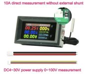
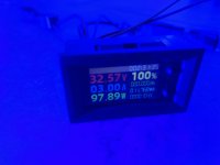
(I have since posted the answer to my own question, I had improperly connected the 9-in-1 multimeter. See my updated reply to this post on page 3. I included a picture of my recent testing of the NUBB24 diode running at 3A.)


DISREGARD THIS POST—— SEE PAGE 3

Another discussion side topic, with using my li-po batteries to run drivers for the NUB diode array series of the 445nm blue lasers, I really haven’t seen a Vf increase when pushing. 4-5+ Amps? I have in my possession, NUBM31, NUBM37, NUBM35, NUBM38, NUBB23 and NUBB24 arrays and so far, none of them have had the same increase as we see with the NUBM47, NUBMOF, or Osram 8W diodes? With pushing 5+Amps, you would think you would see 4.4-4.6Vf? For the NUBB24, you would think you when then see the diode array pulling closer to 33-34Vf? But that’s not the case at all, with my experience, with the rise in current, and driving them for 30-40seconds, I see a drop in Vf and then they stabilize around 0.12V lower, they should pull 4V at 3A, but they actually pull less.. I’m not sure if this is happening because I’m running TEC plates and fans for cooling, and I don’t let the temps ever exceed 50-60*C at the heatsink.. I’m going to hook up my NUBB24 setup tonight and post my results pushing 3A, 4A, 5A, and maybe 6A.. with the data sheet info, they appear to be pretty close to the NUBMOF in terms of output.. that would be awesome if they are because pushing them to 5+ A should yield 8W+.. putting the NUBB24 around 60W, and the NUBB28 in the 80W range, and that’s modest, they could easily handle 5.5-6A and yield 8.5-9W per diode.. I wish I had a bigger LPM..
 

Attachments

  • IMG_4778.jpeg
    IMG_4778.jpeg
    874.1 KB · Views: 1
Last edited:


Back
Top