Welcome to Laser Pointer Forums - discuss green laser pointers, blue laser pointers, and all types of lasers

LPF Donation via Stripe | LPF Donation - Other Methods

Links below open in new window

ArcticMyst Security by Avery

Solid Brass Bar for laser housing?(pics and video included)

gksudo

0
Joined
Sep 2, 2011
Messages
54
Points
0
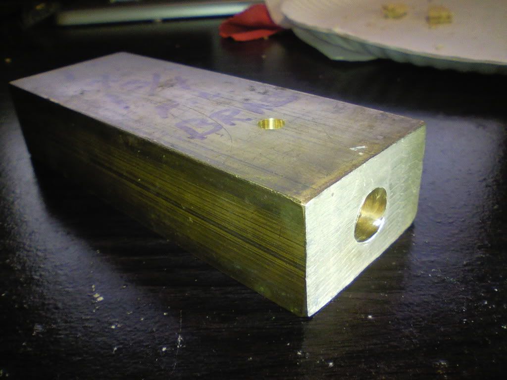
Hello all. I've recently come across a solid brass bar. It is very heavy and would make a good (lab laser? What do you call desk lasers?) unit for placing and playing with. I've decided I don't want handheld, I want steady desk piece.

1080p HD video of the product in question

I wish to put a stable driver circuit on this (or hopefully in a shape that will fit into a drilled hole on the bar itself

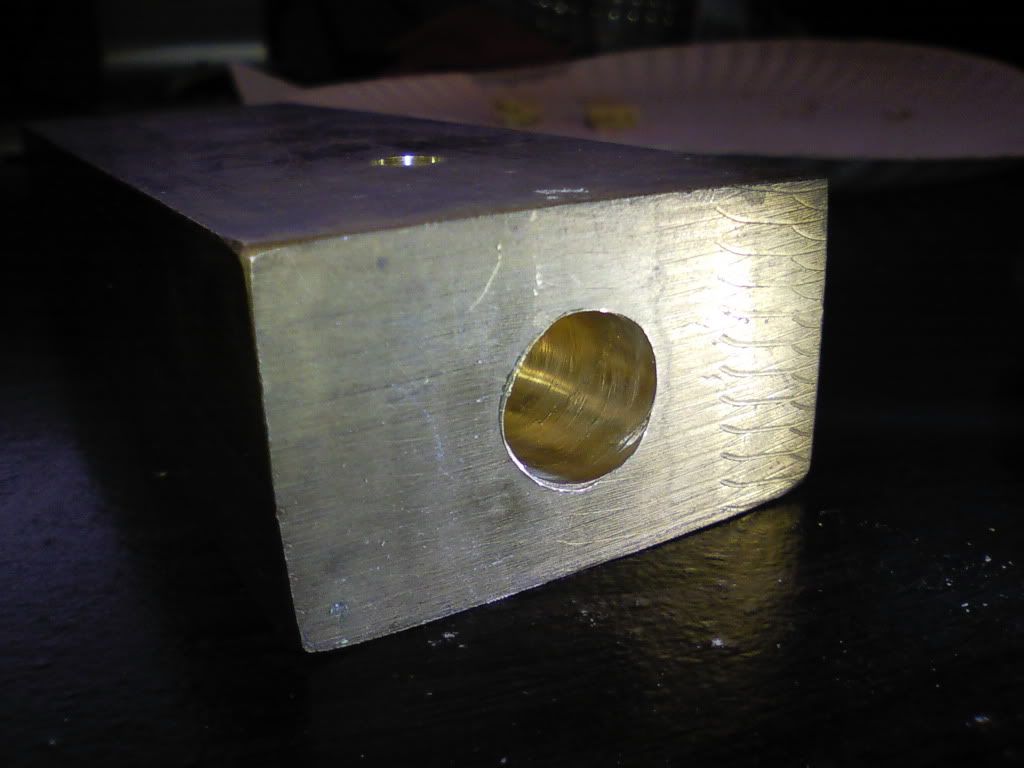
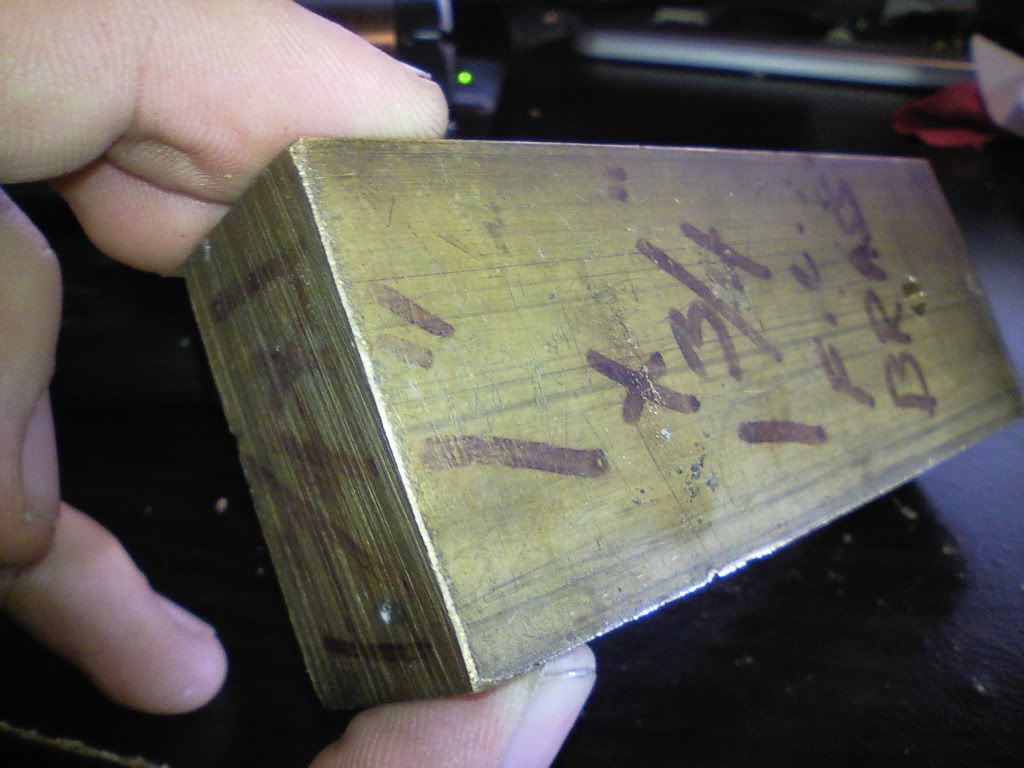
Front Area view of the bar
0904110105.jpg


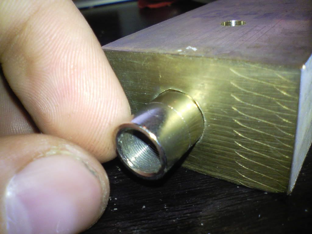
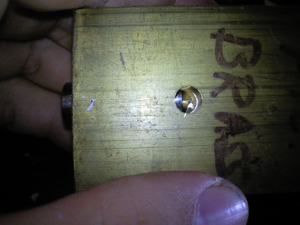
Closeup of hole drilled for aixiz
0904110105a.jpg


Aixiz fits nicely into the spot. I'll at thermal paste as well.
0904110106.jpg


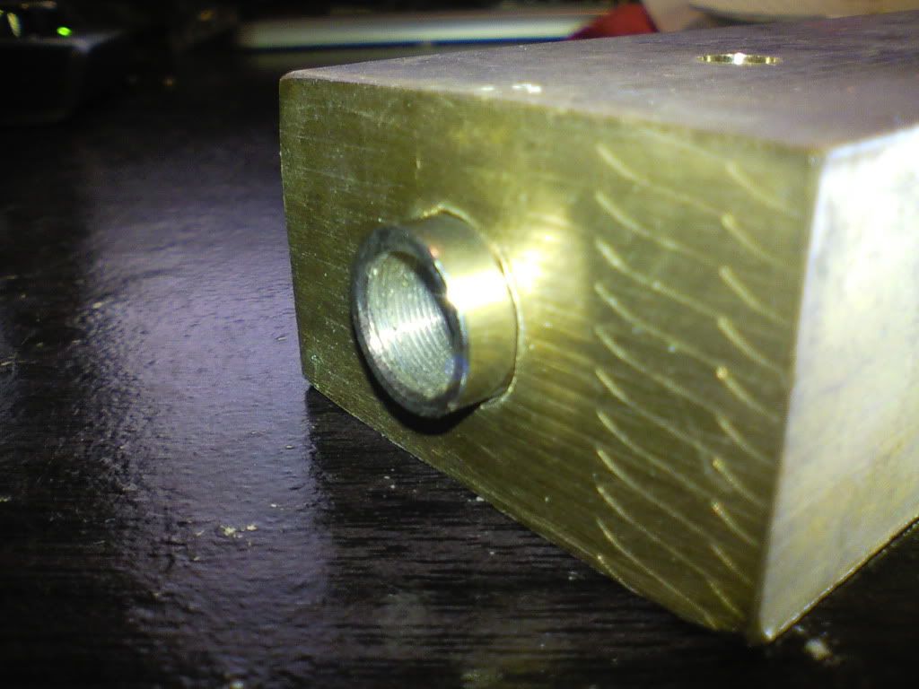
Aixiz pressed all the way in
0904110107.jpg


Top hole for module eject
0904110107a.jpg


Rear of brass bar. I was gonna drill a spot for the driver(have a link to a small one I can use? I can make any size hole, but the smaller the better)
0904110108.jpg


So yeah. I think it will work great. Here's all what I wish to have in this brass piece:


1w 445nm laser diode

A driver for that diode, have an idea of a good fit? I can drill any size hole.

Wires to attach to power.


Overall desired features:

I am looking to end up with a laser which has no duty cycle at 1W. The driver should accept a versatile range of power input up to 15 volts, though I can settle for a (better fitting) driver that uses any other amount of power.

I've been searching for hours trying to decide what I wanted to make. If you could answer a few questions, that'd be great!

Question 1:
Can you point me to a driver which can run a watt of laser power with no overheat?

Question 2:
Would it be easier to just make a simple lm317 current regulator circuit really small and add bolt the LM317 regulator to the outside of the bar for good heatsinking?

Question 3:
Do you really think having a 1 watt 445nm laser inside a giant brass bar will keep it cool(and driver too) with 100% duty cycle?

Polished up a bit, and this might look really really nice!!

I shall provide pictures every step of the way, as well as rep+ any person's who answer my 3 important questions helpfully. ;)
 
Last edited:


Johnyz

0
Joined
Jul 19, 2010
Messages
421
Points
0
Answer 1: You can use Jib's Linear Driver set at 1A or 1.25A. It probably won't overheat if you heatsink it properly, an example is shown in the thread.
Answer 2: You need to use a mica sheet to make sure there is no electrical contact, since LM317 TO220 heat pad is connected to Vout pin. I managed to kill one diode with that.
Answer 3: Yes it will, it's pretty huge. In worst case, you can add a fan.
 
Joined
Dec 17, 2010
Messages
1,144
Points
48
Answer 1: You can use Jib's Linear Driver set at 1A or 1.25A. It probably won't overheat if you heatsink it properly, an example is shown in the thread.
Answer 2: You need to use a mica sheet to make sure there is no electrical contact, since LM317 TO220 heat pad is connected to Vout pin. I managed to kill one diode with that.
Answer 3: Yes it will, it's pretty huge. In worst case, you can add a fan.

Unfortunately, Jib is not making linedrives any time in the forseeable future. :(

I would go with building your own, or use a FlexMod P3 if you don't mind the $39 price tag. :)
 
Last edited:
Joined
Oct 24, 2009
Messages
2,555
Points
48
Well i got a driver, it has some interesting features that most others dont have.
20110904121017.jpg

Right now i am etching my own board but once my layout is done i will be ordering a lot of them.
now to puke out info on it.
constant current source designed to provide a precise constant current starting from a varying input voltage source. The main target is to replace discrete components solution for driving LEDs in low voltage applications such as 5 V, 12 V or 24 V giving benefits in terms of precision, integration and reliability.

The current is set with external resistor up to 2 A with a ± 10 % precision; a dedicated pin allows implementing PWM dimming. An external capacitor allows setting the slope for the current rise from tens of microseconds to tens of milliseconds allowing reduction of EMI.

An open-drain pin output provides information on load disconnection condition.

* Up to 40 V input voltage
* Less than 0.5 V voltage overhead
* Up to 2 A output current
* PWM dimming pin
* Shutdown pin
* LED disconnection diagnostic
* Slope control with external cap
Best of all no high powered resistors or anything needed. i have one of these in my scanners and im using it as TTL works great.
They say 2A but i keep them at 1.5A
And the slope or slow increase in power to the laser when its first turned on is an amazing feature that will prolong the life more than most other drivers
btw if your a circuit board designer send me a pm always looking to make the board smaller
 

Johnyz

0
Joined
Jul 19, 2010
Messages
421
Points
0
Lemme guess: switched mode buck driver? CG on making a working one, these features are nice, too.
 

benmwv

0
Joined
Sep 10, 2010
Messages
1,380
Points
48
Ive got a copper bar just about the same size as that, only twice as long. I think now I'm gonna have to make mine into a labby too.

@kiyoukan

I think I've actually looked at making a driver from the same IC. Thats a PAM one right?
 

Johnyz

0
Joined
Jul 19, 2010
Messages
421
Points
0
Rocket689: Wait, what? Why?
Benmwv:Twice as long? Why don't you just cut it in half and make two?
 
Last edited:
Joined
Oct 24, 2009
Messages
2,555
Points
48
nope all my ics are from st micro.
I get any and all st micro chips for free.
So i can cut the cost down.
once i start selling them they will be around 12 to 15 shipped.
i also bought a chip of dx that has pwm modes and such that i am going to implement.
And the version with modes will be around 18 to 22.
The cost of each driver is less than 3$ when your not paying for most of the parts but the time is a bitch.
 

benmwv

0
Joined
Sep 10, 2010
Messages
1,380
Points
48
Rocket689: Wait, what? Why?
Benmwv:Twice as long? Why don't you just cut it in half and make two?

That is the plan! I could probably do three actually, but will only do two so I get max heatsinking.

nope all my ics are from st micro.
I get any and all st micro chips for free.
So i can cut the cost down.
once i start selling them they will be around 12 to 15 shipped.
i also bought a chip of dx that has pwm modes and such that i am going to implement.
And the version with modes will be around 18 to 22.
The cost of each driver is less than 3$ when your not paying for most of the parts but the time is a bitch.

Oh well I was looking at making a very similar driver with a PAM IC recently but I doubt I could do it cheaper than that.
 
Joined
Dec 17, 2010
Messages
1,144
Points
48
Rocket689: Wait, what? Why?
Benmwv:Twice as long? Why don't you just cut it in half and make two?

This is a quote from Jib's sales page.

"Furthermore, I will be taking a break from LPF and driver making/R&D as I have to prepare for the possibility I might not have employment by the end of the month. I will continue to sell what I have in stock but until things settle down I will not be building anymore."

That was a sad day. All of the drivers sold pretty much instantly. :(

There are still some 444ma ones left if someone wants to mod them with the proper resistor.
 
Joined
Oct 24, 2009
Messages
2,555
Points
48
well soon there will be new ones.
Btw how did the jib drivers do as far as heat at 1.5A? or 2A?
 

gksudo

0
Joined
Sep 2, 2011
Messages
54
Points
0
I can buy one of these when you are ready.
Well i got a driver, it has some interesting features that most others dont have.
20110904121017.jpg

Right now i am etching my own board but once my layout is done i will be ordering a lot of them.
now to puke out info on it.
constant current source designed to provide a precise constant current starting from a varying input voltage source. The main target is to replace discrete components solution for driving LEDs in low voltage applications such as 5 V, 12 V or 24 V giving benefits in terms of precision, integration and reliability.

The current is set with external resistor up to 2 A with a ± 10 % precision; a dedicated pin allows implementing PWM dimming. An external capacitor allows setting the slope for the current rise from tens of microseconds to tens of milliseconds allowing reduction of EMI.

An open-drain pin output provides information on load disconnection condition.

* Up to 40 V input voltage
* Less than 0.5 V voltage overhead
* Up to 2 A output current
* PWM dimming pin
* Shutdown pin
* LED disconnection diagnostic
* Slope control with external cap
Best of all no high powered resistors or anything needed. i have one of these in my scanners and im using it as TTL works great.
They say 2A but i keep them at 1.5A
And the slope or slow increase in power to the laser when its first turned on is an amazing feature that will prolong the life more than most other drivers
btw if your a circuit board designer send me a pm always looking to make the board smaller
 
Joined
Oct 24, 2009
Messages
2,555
Points
48
well i will keep you updated.
I have enough chips to make roughly 45.
but just need the boards. currently looking for the best place to get these boards made.
Also i need round battery terminal boards.
But should be ready in around 2 weeks


Top