- Joined
- Oct 22, 2011
- Messages
- 8
- Points
- 0
Hey guys, putting together my first laser. Long story short ran into a snag.
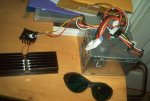
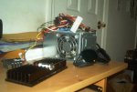
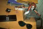
I'm using an old computer's power supply hooked up to an LM317 driver (current around 240 mA). The diode I'm using is closed can red (650 nm; 250 mW I believe).
I just hooked up the diode to everything to make sure it worked before going through the trouble of soldering it up and it lit up brilliantly (rejoice!), so I went ahead and soldered the wires on.
I plugged it in again to make sure it worked before I pressed it, and that's when my heart sunk - it didn't light up at all. So, after cursing and moaning I desoldered everything and hooked the wires up like I had originally (just looped around the correct pins), and voila! It lit up again, just as bright as before.
So I wanted to get your guys' opinion on this, as I have absolutely no idea why it didn't work when soldered. A friend suggested perhaps the solder offers too much resistance to the current, but I've never heard of that happening before. Also, I had twisted the wire around the pins when I soldered them on, to ensure an adequate connection (as a faulty connection might've been the culprit), so I don't think that could be an issue.
Anyway, any advice would be greatly appreciated. Thanks in advance for your help.


