brianpe
0
- Joined
- Dec 26, 2012
- Messages
- 56
- Points
- 18
I wanted to dust off my engineering skills and build my own LPM. Something simple with a pre-calibrated Ophir head and voltmeter. So really, all I built was a power supply. The supply runs off a single 9v battery. That is fed to a 7805 to provide stable power to the volt meter and to a DC-DC converter to upconvert to +/- 15v for the Ophir. I read on this forum of some folks having trouble with noise from the converter damaging the Ophir's amplifier, so I routed the output of the converter to a pair of 7812 / 7912 regulators and some reasonable filter capacitors. And I was careful to load the converter enough to ensure it stays stable, since the Ophir draws very little current.
And then I put it in a box that is entirely too big. But it looks nice.
Update: I've attached a zip containing the board, schematic and library files. You can use the free version of CadSoft's Eagle to generate gerbers for board manufacturing. If I could do it again I might mount the DVM connector on the opposite side of the board to give the boards more clearance. The DVM header has rather short pins for this type of mount.
Pictures:

Empty board, ready for stuffing.
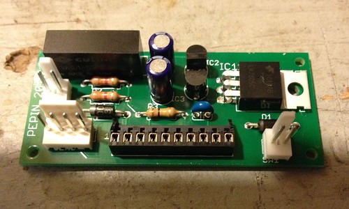
Fully stuffed board.
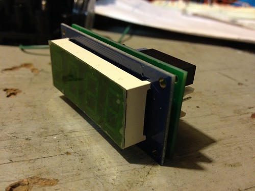
I designed the board to piggy-back right onto the back of the volt meter.
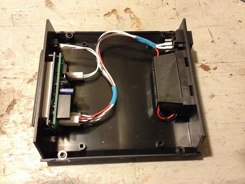
Like I said: the case is way too big.
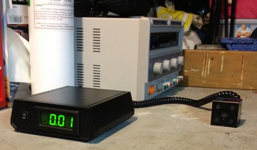
With the sensor connected it runs pretty close to zero. I find that this depends a bit on the ambient temperature. In the garage where it is colder it tends to be +1 or +2. At room temperature it runs at zero.
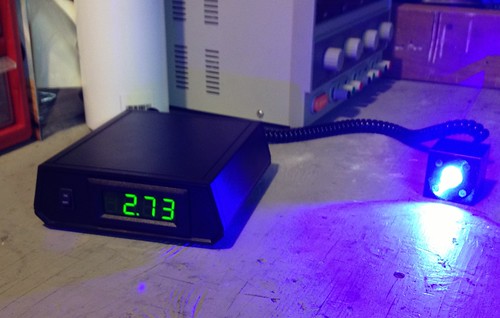
This seems to be pretty accurate. That's a 9mm diode driven at 2.1 amps.
Thanks for looking!
And then I put it in a box that is entirely too big. But it looks nice.
Update: I've attached a zip containing the board, schematic and library files. You can use the free version of CadSoft's Eagle to generate gerbers for board manufacturing. If I could do it again I might mount the DVM connector on the opposite side of the board to give the boards more clearance. The DVM header has rather short pins for this type of mount.
Pictures:

Empty board, ready for stuffing.

Fully stuffed board.

I designed the board to piggy-back right onto the back of the volt meter.

Like I said: the case is way too big.

With the sensor connected it runs pretty close to zero. I find that this depends a bit on the ambient temperature. In the garage where it is colder it tends to be +1 or +2. At room temperature it runs at zero.

This seems to be pretty accurate. That's a 9mm diode driven at 2.1 amps.
Thanks for looking!
Attachments
Last edited:


