

- Joined
- Oct 26, 2007
- Messages
- 5,438
- Points
- 83
This is a mirror of an excellent tutorial on making a linear current regulator circuit using transistors. Though originally for LEDs, the circuit can be applied to lasers as well, and I have used it extensively for analog dimming. I've found this tutorial very helpful in understanding transistor circuits for lasers and LEDs.
Unfortunately, the original tutorial at the Candle Power Forums used images that were hosted on a now-down site. I recently located a copy of the circuit diagram used in the tutorial, and felt it would be good to mirror a complete copy of the original tutorial here to not lose it to Internet dilapidation. The original tutorial, like this mirror, is licensed under a Creative Commons Attribution-Noncommercial-Share Alike 3.0 License. The tutorial is not modified in any way aside from formatting.
Super-Simple Power MOSFET Linear Current Regulator
The most important thing about feeding a power LED is the current flow through the LED. As such a good constant-current supply is a must.
But, building one is a pain.
The easiest known constant-current circuit making the DIY rounds is based on the LM317 voltage regulator. By connecting a resistor across the adjust and output pins and tying its adjust lead to the load, the LM317 becomes a linear current regulator instead of regulating voltage. Two parts and a heatsink and that's it.
The downside is that the LM317 needs at least 3 volts of overhead (the difference between load and supply voltages) to operate this way, and the extra will be converted to heat in the sense resistor and the LM317 itself. This can be exceptionally wasteful if you're working with a low-voltage supply such as batteries. The heat can also be problematic if you're limited on space or cannot provide much of a heatsink.
There is a better way. Presenting, the power MOSFET linear current regulator, inspired by and based on the Instructables post "Circuits for using High Power LED's" by Dan.

This circuit is about as simple as it gets. So simple, in fact, that adding PWM input support almost doubles the parts count!
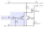
Since PWM control is optional, let's ignore the shaded parts for a moment and discuss the actual regulator itself, which uses R1, R2, Q1, and Q2.
The design is elegantly simple. Q1 operates entirely in linear mode and acts as a variable resistor to control current through the load. R1 keeps the gate of Q1 pulled to positive voltage so that Q1 starts up turned on. As the current begins to flow through the load, Q1, and R2, the voltage drop across R2 increases. When the drop across R2 reaches the "knee" or state-transition voltage for the emitter-base junction of Q2, Q2 begins to switch on, and in so doing starts to pull the gate of Q1 to ground. This causes Q1 to increase its resistance, which decreases current flow through itself, the load, and R2, which decreases the drop across R2, which causes Q2 to let Q1's gate float back toward positive supply, which increases the current flow. Within a few milliseconds, the current flow stabilizes around a specific set point determined by the value of R2. Due to the design of the circuit, the required supply voltage overhead is only about 1.2 volts, less than half of what a LM317 regulator circuit requires.
As the value of R2 is based on the transition emitter-base voltage of Q2, calculating it is easy: all you need is Ohm's Law and an idea what voltage to use. Most conventional silicon general-purpose NPN transistors switch fully at around 0.7VDC and start to transition from off to on at 0.56-0.58VDC. Assuming a transition voltage of 0.58VDC and a target load current of 750mA, the math is as follows:
Calculating the power dissipation for R2 under normal operation is then a matter of Watt's Law:
In this case a half-watt resistor will work but a one-watt would have a safety margin of double. The nearest standard value would be 0.75 ohm, which would give an actual limit of ~733mA in the above example. To achieve the same output current from a LM317 circuit you'd need a 1.6 ohm resistor rated for 2 watts, as the dissipation would be 0.9 watt - a loss of over double what we'll waste as heat here!
The circuit's only real disadvantage is that it doesn't fail gracefully - by design, it tries to push as much current through the load as it can as long as the voltage across R2 doesn't exceed what starts to turn Q2 on. So, for increased fault tolerance, the power rating for R2 could be selected based on the worst-case scenario of the maximum amount of available current flow in the event of a catastrophic failure: a short across both the load and Q1. For that, simply calculate dropping the supply power (voltage times current) across R1. It's generally cheaper to simply use a fuse rated for just above the desired current set point, though, as a power supply providing 1A @ 12VDC would require a 15-watt resistor for R2 and this would be far more costly than a simple fuse.
Dissipation through the MOSFET under operating conditions is calculated the same way, only the voltage used in the calculation should be the supply voltage so that the heatsink selection will account for the worst-case scenario of a dead-shorted load at the target current. In the above example, assuming a 12VDC supply and 750mA current limit, the math works out as follows:
The IRF520 listed in the schematic is rated to handle 9.2A @ 100VDC, and can dissipate 60 watts, so this part will work perfectly well in this configuration with a modest heatsink.
And now the fault-tolerant approach - dissipation through Q1 with a shorted load. Again, simply calculate the maximum supply power that Q1 will see. If the supply is unregulated and capable of large current flows in short time spans (e.g., batteries), again a fuse would be wise as a last-ditch protective measure against catastrophic failures by blowing the circuit open so it cannot try to short the supply. If the set current is 750mA, a 1A-1.5A fuse in series with this circuit would be a wise, and relatively inexpensive, addition - all the more so for portable projects using lithium batteries, given how these like to catch fire (and for nonrechargeable lithium primaries, explode) when shorted.
The only limiting factors on load current and supply voltage relate to the components - using a suitable resistor for R2, this circuit can easily regulate up to a few amps of current in as little as one square inch of board space. The values shown in the schematic will regulate to ~700mA at any supply voltage from ~1.2VDC to about 40VDC, which is the limit for the 2N3904.
If you need precision, the easiest way to get it is to build a test circuit with a fixed supply (12VDC is a great value, but use the desired or intended supply voltage if there's a need to be precise), a dead short for a load, and a 100 ohm resistor for R2. This will set the current limit to about 6mA. Once the circuit is powered up, measure the drop across R2 to determine the exact transition voltage for Q2, and calculate a specific value for R2 for your current requirements based on the math described earlier.
Now, about that PWM stuff...
The extra parts for PWM support include Q3, R3, and R4 - these are blue shaded in the schematic. Since Q3 is a PNP transistor and R4 biases its base to ground, Q3 starts up turned on and pulls Q1's gate to ground regardless of what Q2 is doing, and this forces both Q1 and Q2 to turn off. R3 limits current draw to the PWM signal source. Provide a positive voltage greater than ~0.7VDC to Q3 through R3, and Q3 turns off, which allows the rest of the regulator to function as described above. In this manner a PWM signal can be used to vary the brightness of a load of power LEDs, or a simple on-off switch effect can be implemented by merely pulling Q3's base to positive supply with a few milliamperes of current. In this manner it would be possible to use the circuit as a self-current-limiting switch that only needs a tiny little low-current button as its actuator even though the load could be an amp or more.
So, how well does it work?
For LEDs, this circuit is the cat's meow in that it's very simple and wastes very little power if the source and load voltages are close enough to each other. Ideally this circuit works most efficiently with the supply being right at 1.5VDC above the ideal load voltage at the set current. Naturally it'll also be crucial to be able to provide at least the set amount of current.
There will be some ripple depending on the type of load being powered, especially during power-up, but decoupling capacitors could be used to compensate for this if it's a problem. The circuit is flexible enough in design that it can be driven directly from any logic circuit (even at 3.3VDC), so this can be a great front end for a microcontroller acting as a lighting controller.
The circuit is load-type-independent, meaning that it will happily drive resistive, inductive, capacitive, or mixed loads. Capacitive loads may well experience slower charge times, as the circuit will clamp the charge current. Inductive loads should be paralleled with a reverse-polarity diode (and in some cases, also a proper snubber capacitor) to suppress any back-EMF from the load when power is disconnected so that the voltage spike won't damage the MOSFET. (Most power MOSFETs include integrated protection diodes, but this should never be relied upon as the sole protection mechanism.)
Amusingly enough, with proper component selection it's possible to use this circuit as the driver stage for a single-ended (e.g., digital/class-D) audio power amplifier, which would make such an amp self-protected against a shorted voice coil or bad capacitor in a crossover network. This has not been tested as of this writing, though, so this implementation is not at all guaranteed. So, YMMV. (Your Mileage May Vary.)
LEDs are an interesting load to drive, in that they want variable voltage at a fixed amount of current, with the voltage being sought as the current reaches the desired amount. If the power supply cannot deliver enough voltage to drive the load at the proper current but does have adequate current capacity, it'll do what it can with what it has. For example, if four series-connected LEDs as a load wanting 350mA @ 11.7VDC total are used, and the supply is rated for 1A @ 12VDC, there's not enough overhead to accommodate the full desired load voltage but there's plenty of current capacity. In that case the circuit will produce a reduced voltage across the load (specifically, Vss - ~0.6VDC, or ~11.4VDC in this example) and the power through the load will seek equilibrium with the load's desired voltage and current; the circuit will seek to and center on the closest match to the set point that it can get the load to accept with the reduced load voltage.
If the power supply cannot deliver enough current to reach the set point, Q1 will go full-on and stay there, the circuit will fall out of regulation and just push as much current as it can get out of the supply. It's important to keep in mind that the circuit is not voltage-dependent, and the voltage through the load will climb almost to Vss (well, Vss minus the drop across R2, which will vary with available current that can be pulled from the power supply) if the load doesn't clamp it naturally. It's also important to be aware of supply voltage droop if the power supply is insufficient for the load's desired voltage and the circuit's set current - a decreasing Vss will further decrease the available load voltage. LED loads tend to auto-clamp the load voltage to their junction voltage totals at a given current level, so they tend to self-regulate the circuit's voltage in undercurrent situations.
And there you have it - a ridiculously simple, relatively efficient, inexpensive linear constant-current regulator that only requires four parts (or seven if you need switching/PWM).
Unfortunately, the original tutorial at the Candle Power Forums used images that were hosted on a now-down site. I recently located a copy of the circuit diagram used in the tutorial, and felt it would be good to mirror a complete copy of the original tutorial here to not lose it to Internet dilapidation. The original tutorial, like this mirror, is licensed under a Creative Commons Attribution-Noncommercial-Share Alike 3.0 License. The tutorial is not modified in any way aside from formatting.
Super-Simple Power MOSFET Linear Current Regulator
The most important thing about feeding a power LED is the current flow through the LED. As such a good constant-current supply is a must.
But, building one is a pain.
The easiest known constant-current circuit making the DIY rounds is based on the LM317 voltage regulator. By connecting a resistor across the adjust and output pins and tying its adjust lead to the load, the LM317 becomes a linear current regulator instead of regulating voltage. Two parts and a heatsink and that's it.
The downside is that the LM317 needs at least 3 volts of overhead (the difference between load and supply voltages) to operate this way, and the extra will be converted to heat in the sense resistor and the LM317 itself. This can be exceptionally wasteful if you're working with a low-voltage supply such as batteries. The heat can also be problematic if you're limited on space or cannot provide much of a heatsink.
There is a better way. Presenting, the power MOSFET linear current regulator, inspired by and based on the Instructables post "Circuits for using High Power LED's" by Dan.
This circuit is about as simple as it gets. So simple, in fact, that adding PWM input support almost doubles the parts count!
Since PWM control is optional, let's ignore the shaded parts for a moment and discuss the actual regulator itself, which uses R1, R2, Q1, and Q2.
The design is elegantly simple. Q1 operates entirely in linear mode and acts as a variable resistor to control current through the load. R1 keeps the gate of Q1 pulled to positive voltage so that Q1 starts up turned on. As the current begins to flow through the load, Q1, and R2, the voltage drop across R2 increases. When the drop across R2 reaches the "knee" or state-transition voltage for the emitter-base junction of Q2, Q2 begins to switch on, and in so doing starts to pull the gate of Q1 to ground. This causes Q1 to increase its resistance, which decreases current flow through itself, the load, and R2, which decreases the drop across R2, which causes Q2 to let Q1's gate float back toward positive supply, which increases the current flow. Within a few milliseconds, the current flow stabilizes around a specific set point determined by the value of R2. Due to the design of the circuit, the required supply voltage overhead is only about 1.2 volts, less than half of what a LM317 regulator circuit requires.
As the value of R2 is based on the transition emitter-base voltage of Q2, calculating it is easy: all you need is Ohm's Law and an idea what voltage to use. Most conventional silicon general-purpose NPN transistors switch fully at around 0.7VDC and start to transition from off to on at 0.56-0.58VDC. Assuming a transition voltage of 0.58VDC and a target load current of 750mA, the math is as follows:
R = V / I
R = 0.58VDC / 0.750A
R = 0.773 Ohms
R = 0.58VDC / 0.750A
R = 0.773 Ohms
Calculating the power dissipation for R2 under normal operation is then a matter of Watt's Law:
P = V * I
P = 0.58VDC * 0.750A
P = 0.435 Watt
P = 0.58VDC * 0.750A
P = 0.435 Watt
In this case a half-watt resistor will work but a one-watt would have a safety margin of double. The nearest standard value would be 0.75 ohm, which would give an actual limit of ~733mA in the above example. To achieve the same output current from a LM317 circuit you'd need a 1.6 ohm resistor rated for 2 watts, as the dissipation would be 0.9 watt - a loss of over double what we'll waste as heat here!
The circuit's only real disadvantage is that it doesn't fail gracefully - by design, it tries to push as much current through the load as it can as long as the voltage across R2 doesn't exceed what starts to turn Q2 on. So, for increased fault tolerance, the power rating for R2 could be selected based on the worst-case scenario of the maximum amount of available current flow in the event of a catastrophic failure: a short across both the load and Q1. For that, simply calculate dropping the supply power (voltage times current) across R1. It's generally cheaper to simply use a fuse rated for just above the desired current set point, though, as a power supply providing 1A @ 12VDC would require a 15-watt resistor for R2 and this would be far more costly than a simple fuse.
Dissipation through the MOSFET under operating conditions is calculated the same way, only the voltage used in the calculation should be the supply voltage so that the heatsink selection will account for the worst-case scenario of a dead-shorted load at the target current. In the above example, assuming a 12VDC supply and 750mA current limit, the math works out as follows:
P = V * I
P = 12VDC * 0.750A
P = 9 watts
P = 12VDC * 0.750A
P = 9 watts
The IRF520 listed in the schematic is rated to handle 9.2A @ 100VDC, and can dissipate 60 watts, so this part will work perfectly well in this configuration with a modest heatsink.
And now the fault-tolerant approach - dissipation through Q1 with a shorted load. Again, simply calculate the maximum supply power that Q1 will see. If the supply is unregulated and capable of large current flows in short time spans (e.g., batteries), again a fuse would be wise as a last-ditch protective measure against catastrophic failures by blowing the circuit open so it cannot try to short the supply. If the set current is 750mA, a 1A-1.5A fuse in series with this circuit would be a wise, and relatively inexpensive, addition - all the more so for portable projects using lithium batteries, given how these like to catch fire (and for nonrechargeable lithium primaries, explode) when shorted.
The only limiting factors on load current and supply voltage relate to the components - using a suitable resistor for R2, this circuit can easily regulate up to a few amps of current in as little as one square inch of board space. The values shown in the schematic will regulate to ~700mA at any supply voltage from ~1.2VDC to about 40VDC, which is the limit for the 2N3904.
If you need precision, the easiest way to get it is to build a test circuit with a fixed supply (12VDC is a great value, but use the desired or intended supply voltage if there's a need to be precise), a dead short for a load, and a 100 ohm resistor for R2. This will set the current limit to about 6mA. Once the circuit is powered up, measure the drop across R2 to determine the exact transition voltage for Q2, and calculate a specific value for R2 for your current requirements based on the math described earlier.
Now, about that PWM stuff...
The extra parts for PWM support include Q3, R3, and R4 - these are blue shaded in the schematic. Since Q3 is a PNP transistor and R4 biases its base to ground, Q3 starts up turned on and pulls Q1's gate to ground regardless of what Q2 is doing, and this forces both Q1 and Q2 to turn off. R3 limits current draw to the PWM signal source. Provide a positive voltage greater than ~0.7VDC to Q3 through R3, and Q3 turns off, which allows the rest of the regulator to function as described above. In this manner a PWM signal can be used to vary the brightness of a load of power LEDs, or a simple on-off switch effect can be implemented by merely pulling Q3's base to positive supply with a few milliamperes of current. In this manner it would be possible to use the circuit as a self-current-limiting switch that only needs a tiny little low-current button as its actuator even though the load could be an amp or more.
So, how well does it work?
For LEDs, this circuit is the cat's meow in that it's very simple and wastes very little power if the source and load voltages are close enough to each other. Ideally this circuit works most efficiently with the supply being right at 1.5VDC above the ideal load voltage at the set current. Naturally it'll also be crucial to be able to provide at least the set amount of current.
There will be some ripple depending on the type of load being powered, especially during power-up, but decoupling capacitors could be used to compensate for this if it's a problem. The circuit is flexible enough in design that it can be driven directly from any logic circuit (even at 3.3VDC), so this can be a great front end for a microcontroller acting as a lighting controller.
The circuit is load-type-independent, meaning that it will happily drive resistive, inductive, capacitive, or mixed loads. Capacitive loads may well experience slower charge times, as the circuit will clamp the charge current. Inductive loads should be paralleled with a reverse-polarity diode (and in some cases, also a proper snubber capacitor) to suppress any back-EMF from the load when power is disconnected so that the voltage spike won't damage the MOSFET. (Most power MOSFETs include integrated protection diodes, but this should never be relied upon as the sole protection mechanism.)
Amusingly enough, with proper component selection it's possible to use this circuit as the driver stage for a single-ended (e.g., digital/class-D) audio power amplifier, which would make such an amp self-protected against a shorted voice coil or bad capacitor in a crossover network. This has not been tested as of this writing, though, so this implementation is not at all guaranteed. So, YMMV. (Your Mileage May Vary.)
LEDs are an interesting load to drive, in that they want variable voltage at a fixed amount of current, with the voltage being sought as the current reaches the desired amount. If the power supply cannot deliver enough voltage to drive the load at the proper current but does have adequate current capacity, it'll do what it can with what it has. For example, if four series-connected LEDs as a load wanting 350mA @ 11.7VDC total are used, and the supply is rated for 1A @ 12VDC, there's not enough overhead to accommodate the full desired load voltage but there's plenty of current capacity. In that case the circuit will produce a reduced voltage across the load (specifically, Vss - ~0.6VDC, or ~11.4VDC in this example) and the power through the load will seek equilibrium with the load's desired voltage and current; the circuit will seek to and center on the closest match to the set point that it can get the load to accept with the reduced load voltage.
If the power supply cannot deliver enough current to reach the set point, Q1 will go full-on and stay there, the circuit will fall out of regulation and just push as much current as it can get out of the supply. It's important to keep in mind that the circuit is not voltage-dependent, and the voltage through the load will climb almost to Vss (well, Vss minus the drop across R2, which will vary with available current that can be pulled from the power supply) if the load doesn't clamp it naturally. It's also important to be aware of supply voltage droop if the power supply is insufficient for the load's desired voltage and the circuit's set current - a decreasing Vss will further decrease the available load voltage. LED loads tend to auto-clamp the load voltage to their junction voltage totals at a given current level, so they tend to self-regulate the circuit's voltage in undercurrent situations.
And there you have it - a ridiculously simple, relatively efficient, inexpensive linear constant-current regulator that only requires four parts (or seven if you need switching/PWM).


 ). I like very slow fading speed (the whole rainbow has a period of 1 minute) so that doesn't help either.