Welcome to Laser Pointer Forums - discuss green laser pointers, blue laser pointers, and all types of lasers

LPF Donation via Stripe | LPF Donation - Other Methods

Links below open in new window

ArcticMyst Security by Avery

Simple Laser Power Meter Using IR Thermometer

Joined
Mar 8, 2008
Messages
2,669
Points
48
lasersbee said:
Hey guys.... don't you think a few other members should build this IR based
DIY LPM and test it against a calibrated LPM... before this thread gets
stickied...  :-? :-? :-? :-?

Jerry

I agree...


Warske

0
Joined
Mar 10, 2009
Messages
145
Points
0
Good questions, 691175002, so I took quite a bit of time with the reply...

691175002 said:
...rather skeptical of the magic 3.13
I doubt it is exactly 3.13, but that is the best number I have at the moment, and I believe it will give the 15% accuracy stated.  Someone with an accurate LPM will, I hope, double check this.  If it turns out that I am off by a few percent and the real magic number is, say, 3.3, then I will edit the first post to include the more accurate number.  I had anticipated doing that, and it is one of the reasons I think the initial 15% accuracy statement can be tightened up.

... how did you come up with it anyways considering you don't have a real LPM?
As I mentioned earlier, I used some simple physics to come up with the number.  It may be worth detailing my method in a separate thread if anyone is interested, but basically it involves using a thermal conductor with an accurately known heat capacity and reflectivity.  By measuring the thermal time constant when laser power is applied, the actual amount of power can be derived.  An interesting feature of this is that the thermal resistance doesn't affect the final result (unlike the LPM of this thread).

As a sanity check, I've tested the SLD1239JL-54 laser, and the diodes from some LPC-815 and PHR-803T sleds. Their power vs current curves line up nicely with what has been reported on LPF, but that only gives me ballpark numbers, of course.

The heat dissipation of the black target will vary with its mass/size/thickness/material/shape.
Generally, the thermal resistance (heat dissipation) of a vertical, thermally conductive surface such as aluminum, will vary most strongly with its surface area, while other variables are much less critical.

The mass and thickness (within limits) does not affect steady state dissipation, although it does affect thermal time constant.  As I mentioned in the construction section, "The thickness of the aluminum is not too critical.  It's the surface area that is critical.  The foil I used is the standard household variety...  I have also tested the aluminum from the side of a soft drink can, which was 6 times thicker.  It gives the same readings but takes longer to heat up due to its larger thermal mass."

The material specified is aluminum.  Certainly if someone decided to use plastic wrap for the target instead, the results would be different.

The shape is either round or square, and the sizes were adjusted to make the two read the same.

Not only that, but the ambient room temperature (which will in turn affect convection) and any drafts will have a huge impact on the readings.
Ambient temperature within a normal range doesn't measurably affect the readings.  If you want to learn more about this topic, you can research how convection heat sinks work.

Strong drafts will affect the readings, and for greatest accuracy in the presence of drafts, it is recommended that the meter be shielded from them by putting it in a box such as the one pictured in the construction section.  In an area where there are no fans going, no open windows, no doors being swung, no people running past, you will get the same results whether you enclose the meter or not.  Note that drafts also affect many high end LPMs.

You have addressed this somewhat by specifying dimensions but I doubt that will be accurate enough.
The accuracy of the dimensions is very important.  That is why I showed a picture of a digital micrometer measuring the square target, and I suggested the round target be cut with a specific piece of tubing which is manufactured to rather high tolerances (the different sizes of tubing sold actually nest together with a sliding fit).

For example, if the square target is .510" by .510" instead of exactly a half inch square, this will throw the readings off a little bit.  Doing the math,
(.510 * .510) / (.5 * .5) = 1.040
we see that the surface area is off by 4%, and the readings will be thrown off by roughly the same amount.  While 4% error here would be unfortunate, I think you will agree this is still a better method of measuring your laser's power than seeing whether it will light matches!  And the price is hard to beat.  This gets into the question: "How accurate is accurate enough."

My feeling is that most people can get much closer than .510" if they are careful and give it a couple of tries.

For perfectionists, I would recommend the tubing cutter method.  Note that, once you are set up with that, you can stamp these targets out both quickly and accurately.  Maybe someone would want to go into production and mail them out to folks for a nominal fee.  As an exercise, calculate the material cost per target given that about $6 buys you a roll of aluminum foil (75 square feet!) and a can of paint...

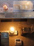
For example, what happens if you move the piece of aluminum foil closer to or against the thermometer?
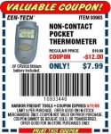
Good question.  I was going to run that experiment, but I thought I would provide my results-so-far when I saw that the IR Thermometer went on sale.  Would have been a shame to miss it.

There isn't any reason I know of to think that distance is especially critical, but if it is much farther the IR Thermometer starts to be able to see around the target (so it will average the ambient into the readings).  Much closer and the air flow around the target (thus the thermal resistance, which is critical) will be affected.  So it's best to keep the target about 1/16" away until someone runs the test (volunteers?).

I think a real test you can do already is get someone else to make one
It looks like that will happen...

or make a few yourself and see how repeatable measurements are across every thermometer.
I actually did quiet a lot of testing on this.  The answer is: incredibly repeatable.

Unfortunately, my gut feeling tells me that when different people build these using different materials and to different tolerances you are going to end up with some pretty major variations.
Based on my tests, if it is done carefully and per the instructions, I think people will be within the 15%.  Of course, many  would call that a pretty major variation.  As I said at the beginning, "... this meter isn't in the same league as more expensive LPM's (which are more accurate and easier to use)..."  But it does cost less, and it is quite useful.


lasersbee and jamilm9, thanks for the rep points!
 

Benm

0
Joined
Aug 16, 2007
Messages
7,896
Points
113
Interesting idea to measure laser power this way!

A few thoughts and things:

The important feature of the paint you use is its absorptivity: how much of the laser light is absorbed. Whatever light the paint doesn't reflect is absorbed and converted to heat.

Another important aspect is IR emissivity, which is not normally indicated for this type of paints, as it is of no importance for normal use. I does affect to what degree the contactless thermometer is able to measure the termperature however. An interesting idea would be to paint one site flat black, and the other side (facing the thermometer) in radiator paint.

As for the size of the sensor disk being an issue in accuracy: You could use a practically infinite sized disk as well, conductivity would still be limited and result in reproducible measurements. Infinite would be large enough to cause to heating on the outer edge, perhaps an inch or two would suffice.
 

Warske

0
Joined
Mar 10, 2009
Messages
145
Points
0
Benm said:
Another important aspect is IR emissivity, which is not normally indicated for this type of paints, as it is of no importance for normal use. I does affect to what degree the contactless thermometer is able to measure the termperature however. An interesting idea would be to paint one site flat black, and the other side (facing the thermometer) in radiator paint.
Thanks for the ideas.  You are right about the effect of emissivity on measuring temperature.  The surprise is that the effect is small unless you are dealing with a highly reflective surface like a mirror.  In fact, the emissivity of black paint and white paint are quite similar.  Here is a table http://www.engineeringtoolbox.com/emissivity-coefficients-d_447.html

The reason is that emissivity involves wavelengths in the far infrared.

If you get one of these thermometers and point it at a white wall or a black wall in the same room, the temperature reading you get will be the same within the resolution of the thermometer.  I was surprised by this myself.

The other interesting thing is that, for this application, the emissivity doesn't matter at all as long as it is consistent.  This is because, if we had a different emissivity than we do, it would just show up as a change in the conversion factor from temperature to watts.  That being the case, it is easiest just to use the same paint on both sides of the foil, even though they serve two completely different purposes.

As for the size of the sensor disk being an issue in accuracy: You could use a practically infinite sized disk as well, conductivity would still be limited and result in reproducible measurements. Infinite would be large enough to cause to heating on the outer edge, perhaps an inch or two would suffice.
I'm not sure I quite understand your idea.  

If the disk is much larger, you get a temperature gradient across the disk because of the thin aluminum.  That is, if you have a focused laser spot heating the center of a very large, thin disk, the center will be higher temperature than the edges because of thermal resistance in the material and cooling at the edge due to convection and radiation.  That thermal resistance will depend on the thickness of the material, which we don't want, because we don't have good control over the thickness.

So the trick is to make the disk small enough so that the thinnest material (in this case standard weight aluminum foil) is still thick enough to minimize the temperature gradient.   The disk could probably be larger than I did make it, but it would need some careful testing to verify that.

Thanks for the good feedback, and let me know if I didn't understand.


pseudolobster, thanks for the +1!
 

Benm

0
Joined
Aug 16, 2007
Messages
7,896
Points
113
You understood right - the infinite-size approach will only work with predictable results if you have material of know thickness and composition. I wonder how much that actually varies between rolls of tinfoil from any particular brand though - possibly less than the variation in accuracy in cutting out disks of certain sizes.

All the factors considerd i do doubt it would be possible to come up with a design that is, say, 10% accurate without calibraton against a know source.

One interesting thing to investigate is to actually create a simple to build known source. Since this design is thermal, a halogen bulb of a certain power and at a certain distance could provide a calibration source. For example, a 100W halogen bulb at 10 cm distance (4pi.r2=1245cm2) would rain down 7.596 mW/cm2 on the disk. Given a 0.5 inch diameter disk, that should result in a reading of 4.9 mW.

I've been working on a thermal sensor design with ~5x5mm square targets making that approach less feasible, but with something this large it could be practical.
 

Warske

0
Joined
Mar 10, 2009
Messages
145
Points
0
Benm said:
Since this design is thermal, a halogen bulb of a certain power and at a certain distance could provide a calibration source. For example, a 100W halogen bulb at 10 cm distance (4pi.r2=1245cm2) would rain down 7.596 mW/cm2 on the disk. Given a 0.5 inch diameter disk, that should result in a reading of 4.9 mW.
I was thinking of doing something like that, but since I couldn't easily validate the reflectivity of the paint across the full spectrum into the far IR, I figured it wouldn't be all that meaningful.

But I was curious what the result would be, and by the time you ran the numbers, I couldn't resist.  I don't have a small high wattage halogen.  That would be nice since it gets a little closer to being a point source.  But I do have a clear, long life incandescent that clocked in at 90 W using a "Kill A Watt" meter, which itself is probably only accurate to 5%.

The filimant is distributed over an area, and the globe is large, both of which could make the results less accurate.

I set it up for 10 cm (plus or minus a few mm) from the laser target to the center of the filament.

My initial temperature was 63.5 F, and 30 seconds after I turned on the light I read a stable 101.9 F.

Using the procedure in the first post, I get
(101.9 - 63.5) * 3.13 = 120.2 mW

Well, 120.2 mW isn't even close to the 4.9 mW you calculated, so I checked the math:

Surface area of sphere at 10 cm =  4 * 3.14159 * 10^2 = 1256.636 cm^2   Check.

The disk I'm using is actually 0.564" in diameter, to give an area of
3.14159 * (0.564 * 2.54 / 2)^2 = 1.611815 cm^2

So the power hitting it from a 90 w incandescent should be about
1.611815 / 1256.636 * 90 * 1000 = 115.44 mW

That suggests the meter is reading high by 120.2 / 115.44 = 1.041
Which is 4.1% high.

That seems pretty good, but I think the error sources in my quick experiment could easily swamp that out, so I can't claim it as validation.  But it is interesting.

Good ideas, thanks!

I've been working on a thermal sensor design with ~5x5mm square targets making that approach less feasible, but with something this large it could be practical.
Maybe your idea would work for it after all.  Lets see, your surface area is 1.6 / .25 = 6.4 times smaller, so you would get about 20 mW from your 100 W halogen.
 

Attachments

  • DIY_Laser_Power_Meter_-_Test.jpg
    DIY_Laser_Power_Meter_-_Test.jpg
    174.4 KB · Views: 1,636
Joined
Jan 2, 2009
Messages
11,800
Points
0
I wish I could give you another point, but it takes a week or two before I can give you another. Very impressive, and your logic is profound. You are on a similar level as Igor IMHO. I cant wait to see how it measures up to a LPM. If it measures up, you will have just given the average hobbyist a very useful, and affordable tool.

Defiantly sticky material. [smiley=thumbsup.gif]
 

Warske

0
Joined
Mar 10, 2009
Messages
145
Points
0
Blu-Ray_Junkie said:
I wish I could give you another point... I cant wait to see how it measures up to a LPM. If it measures up, you will have just given the average hobbyist a very useful and affordable tool.
Thanks for the previous point and the encouraging words.  I did cringe to see all those posts about "How do I measure my laser's power w/o spending a bunch of money" and not be able to offer a reasonable alternative.

It's worth pointing out that you can look at the usefulness of this device on two levels.  On one level it can be used for relative measurements, and on the second level, it can be used for absolute measurements.

For example, let's say you made one of these laser targets but you got the dimensions off by quite a bit.  It isn't going to work for absolute measurements until you calibrate it somehow.  That is, you can't use it to measure mW of laser power.

But you can still use it for making relative measurements.  It can tell you, for instance, that Laser A is 18% more powerful than Laser B.  Or that the power of Laser A has dropped by 4% since the last time you measured it.

Furthermore, since its response is quite flat across different wavelengths (compared to a silicon photodiode like the LaserCheck uses), it can compare lasers of different colors.  (I noted in the first post that with the specified paint, the Mark I target is 1% less sensitive to violet than to red.)

The LaserCheck is quite accurate for red lasers, but the violet lasers not so much.  

Part of the problem is that the Blu-Ray diodes are not all at the same wavelength.  Folks on this forum, such as daguin in his thread "Strange Things About Blu-Ray" http://www.laserpointerforums.com/forums/YaBB.pl?num=1219161671 have noted that violet diodes with the same output power can appear to be very different in brightness.  

The same is true with the LaserCheck: it sees the different wavelengths as different signal levels.  To get an accurate reading for a violet laser, you have to tell it the wavelength, but the problem is that you don't know the exact wavelength.

And even if you know the wavelength, there is a question about how accurate the LaserCheck and similar meters are for violet lasers because the photodiode response curve starts to tail off in that region of the spectrum.

That question, how do I calibrate for violet, was the genesis for the "Power Meter Calibration and Comparison" thread http://www.laserpointerforums.com/forums/YaBB.pl?num=1217029972/0, which was started by pullbangdead almost a year ago and is currently up to 710 posts!

If you have a red laser, a violet laser, a LaserCheck, and an uncalibrated thermal LPM, you can use the combination to get an accurate power reading on the violet laser:
Use the LaserCheck to read the power of the red laser, use the red laser to calibrate the thermal LPM, and then use that to get an accurate reading on the violet laser.  

This gets us to the second level I was talking about.  I still maintain that if constructed carefully with the Mark I target, the LPM described here should be accurate to 15% without further calibration (I know, I know, we still need some independent corroboration of this).  If calibrated against a LaserCheck using a red laser, it should be as accurate as the LaserCheck plus or minus another 3%.  So that is another possible solution to the violet diode problem.
 

Benm

0
Joined
Aug 16, 2007
Messages
7,896
Points
113
Thanks for correcing my calculations - the number felt low as i wrote it down, must have messed up somewhere in the process.

Warske said:
I was thinking of doing something like that, but since I couldn't easily validate the reflectivity of the paint across the full spectrum into the far IR, I figured it wouldn't be all that meaningful.

You should assume the paint is fine: You DO assume its emissivity is close enough to 1 in the IR to make contactless IR measurement viable, which implies it absorption of energy at similar wavelengths (i.e. heat from the lamp) must also be close to 1. Absorptivity and emissivity are exactly the same thing (albedo), we only use either term to indicate purpose (i.e. absorb or emit photons).

In theory it could be such that the albedo of the paint is high in the near-IR, but low in the visible and far-IR (thus yielding too low measurements), but i see no reason to assume that.


Warske said:
That suggests the meter is reading high by 120.2 / 115.44 = 1.041
Which is 4.1% high.

That seems pretty good, but I think the error sources in my quick experiment could easily swamp that out, so I can't claim it as validation.  But it is interesting.

4% is a very promising result - between the size of that lightbulb, not-fully-1 albedo of the paint coat and other disrupting factors such as convection around the sensor disk, it is better than i expected it to be (then again, you could just have been lucky here).

At least it is prove of principle, demonstrating that the sensor and measurement setup does work as expected and works independent of wavelength, even far into the IR - making it usable for 1064 or 808 as well.
 

Benm

0
Joined
Aug 16, 2007
Messages
7,896
Points
113
Also, i could try the lightbulb approach on the smaller target meter.. but that has sensor heating for calibration built in as it is, so it would do little more than asses the target albedo in IR.
 

Warske

0
Joined
Mar 10, 2009
Messages
145
Points
0
Benm said:
You DO assume its emissivity is close enough to 1 in the IR to make contactless IR measurement viable
Actually, I don't assume that. If the emissivity was 0.5, the only thing that would change is the calibration constant.

I may want to run that experiment again a bit more carefully. Maybe it would be useful for other folks trying to calibrate a thermal head from ebay.

Do you have anything in mind for a widely available standard halogen? I thought I might look at car headlamps, the kind w/o the reflector. A slide projector bulb might also work, though I think they are expensive.

Benm said:
Also, i could try the lightbulb approach on the smaller target meter.. but that has sensor heating for calibration built in as it is, so it would do little more than asses the target albedo in IR.
Hey, I just realized you authored "DIY: Laser Power Gauge" http://www.laserpointerforums.com/forums/YaBB.pl?num=1226965719/0
(Sound of hand hitting forehead.) My memory isn't what it used to be. That was/is a great thread. I've got some thoughts on why it was reading high instead of low as expected, and can post those on your thread if interested.

Thanks for all your great feedback. I'll be out of town for a couple days, so won't be able to check here until I get back.
 

Benm

0
Joined
Aug 16, 2007
Messages
7,896
Points
113
I never realized those themometers had gotten that cheap by now. Could be useful for diagnosing electronic circuits as well.
 

Asherz

0
Joined
Jan 18, 2009
Messages
1,623
Points
0
Im trying this out soon :) looks great and will give a rough idea
 
Joined
Jun 16, 2008
Messages
53
Points
0
Harbor Freight also has helping hands available with two clamps and a magnifying glass for $1.89 on sale, so those and the thermometer will get me to take a trip there this weekend (or possibly sooner). Assuming they have one in stock, I'll build one of these as soon as I get home with the materials. Unfortunately, I don't have an LPM, nor do I have any lasers that I am confident in their output levels. I have a 5 mW that I believe to be somewhat overspec'd (although it has recently gotten weaker), a defective 20 mW that starts strong and less than a second later puts out less light than the 5 mW, and a 10 mW that is severely overspec'd (pokes holes in trash bags, electrical tape, etc.).

I'll be getting a BudgetGadgets 50 mW green in soon that, based on reviews, should be close to spec. Additionally, assuming I can fix the botched install, I have a PHR-803T Blu-ray diode, an AixiZ housing, and a fixed 90 mA rckstr driver. Also a good chance I'll be ordering a 50 mW pen from LED Shoppe.

I've got pretty good confidence that this should work properly though. Your math and logic are seemingly flawless and you clearly demonstrate excellent knowledge in the topic. At the very least, it seems to work relatively, so if I purchase an LPM-rated laser off anyone on this forum in the near future (or anyone builds one of these to test), I can compare the output of other lasers relative to the laser in question. The relationship between temperature and laser power is linear, correct? In other words, can I simply take the percentage difference in temperature and then multiply this by the output of the known laser in order to determine the output of the other laser?

tl;dr - will give this a shot soon, let you know how it goes.


Top