Welcome to Laser Pointer Forums - discuss green laser pointers, blue laser pointers, and all types of lasers

LPF Donation via Stripe | LPF Donation - Other Methods

Links below open in new window

ArcticMyst Security by Avery

Setting a Driver Current with the Laser Diode Connected

smana

Member
Joined
Nov 2, 2022
Messages
50
Points
8
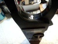
I want to adjust the driver's on-board potentiometer with the laser diode already connected - i.e. no test load.

Do most of you simply turn the potentiometer screw a very small amount, turn the power on, measure the current, turn the power off, and continue this process over and over until the desired current?

Note: When turning the tiny screw on the driver's on-board potentiometer, many recommend turning the power off first to avoid excessive noise and current spikes (which can occur during the turning of the tiny screw) which can exceed the laser diode's amp rating and damage it. Also, the current response to the screw turns is not linear and is therefore a bit unpredictable so its better to take your time and turn the screw very small increments at a time if you decide to do this. Needless to day, the lower the laser diode amp rating, the higher the risk of diode damage with this procedure.

Do you use a standard multimeter, and inductive current meter (clamp meter), or something else?

For my specific situation, I am setting a NUBM07E laser diode (specs: max 3.5Amps, nominal 2.3Amps) to 2.3 Amps using a driver pre-set to 1.6 Amps.
 
Last edited:


WizardG

0
LPF Site Supporter
Joined
May 9, 2011
Messages
1,189
Points
113
Couple problems here. Where do you plan to measure the current? The measurement must be taken at the driver output. the leads from the driver to the diode are rarely long enough for a clamp meter (inductive). If you have to disconnect one leg of the diode to connect a DMM you would be better to go all the way and construct a test load. The pots on many drivers are rather touchy. I wouldn't try it without a test load. At least not again.........
 

smana

Member
Joined
Nov 2, 2022
Messages
50
Points
8
Couple problems here. Where do you plan to measure the current? The measurement must be taken at the driver output. the leads from the driver to the diode are rarely long enough for a clamp meter (inductive). If you have to disconnect one leg of the diode to connect a DMM you would be better to go all the way and construct a test load. The pots on many drivers are rather touchy. I wouldn't try it without a test load. At least not again.........
The leads from the driver to diode will be rather long (at least 3 inches) due to the host setup.

As for having to de-solder one leg of a diode, wouldn't it be possible to simply contact the meter test leads to the solder joints?
 

smana

Member
Joined
Nov 2, 2022
Messages
50
Points
8
Excellent! Thank you for the schematic ! Very helpful.

So I guess you also disconnect the positive leg of the diode (if its already connected).

So if the positive laser diode lead has not been soldered yet, a regular multimeter can be used.

Once the diode leads are soldered and finished, a clamp meter is more convenient since this doesn't require de-soldering of the positive diode lead.
 
Last edited:
Joined
Jul 10, 2015
Messages
9,903
Points
113
I use an inductive meter to set mine with the laser diode connected and you can read from the input side if you know current at a given voltage will be, the bucking drivers are 95% efficient so watts for watts.

For instance a nubm44 draws 4.5A @ 4.5V that's 20.25W ........So on the input side if you use 2 x 18650 fully charged @ 4.2V each which is 8.4V or 8.3V under load @ 2.5A that's 21W or 20.75W under load - 5% loss in the driver 19.71W which is close enough or adjust to 2.55A which at 8.3V adjusted x 0.95 is 20.1W


smana

Member
Joined
Nov 2, 2022
Messages
50
Points
8
Thank you for the info Red Cowboy! I was just looking at those clamp meters, lol.

Since the NUBM44 runs nominally at 6W to 7W of light output while the driver is outputting 20W, this shows how inefficient laser diodes tend to be? If so, that's a big hit in efficiency rating for the laser diode.

I guess the rest of the watts going to the laser diode is being converted to heating up the heat sink/copper module while 5% loss in the driver is going toward heating up the driver chip....
 
Last edited:
Joined
Jul 10, 2015
Messages
9,903
Points
113
Yes 21.15W into the laser diode and about 7.75W out of the laser diode of which 5% is lost in the lens ( G2 )
So there is 13.4W of waste heat at 4.5A ( about 63% loss ) at 4.5A which is overdriven, factory spec is 3.5A which is also usually where the diode is most efficient.

Actually 4.5A flows @ 4.7V for the NUBM44-V2 I had said 4.5V before, however the length of the wire can have a small effect.

At 3.5A it takes 4.5V = 15.75W into the diode and right at 6.4W out - 5% for the lens, 9.35W of waste heat which is about 58% loss.

This is from a cold start and in a heat sink.

It's good to use a laser power meter to verify output.
 

smana

Member
Joined
Nov 2, 2022
Messages
50
Points
8
Yes 21.15W into the laser diode and about 7.75W out of the laser diode of which 5% is lost in the lens ( G2 )
So there is 13.4W of waste heat at 4.5A ( about 63% loss ) at 4.5A which is overdriven, factory spec is 3.5A which is also usually where the diode is most efficient.

Actually 4.5A flows @ 4.7V for the NUBM44-V2 I had said 4.5V before, however the length of the wire can have a small effect.

At 3.5A it takes 4.5V = 15.75W into the diode and right at 6.4W out - 5% for the lens, 9.35W of waste heat which is about 58% loss.

This is from a cold start and in a heat sink.

It's good to use a laser power meter to verify output.
RedCowboy - thank you for the info and numbers ! (and this is why there is such an emphasis on proper heatsinking on this forum, lol).
 
Joined
Jul 10, 2015
Messages
9,903
Points
113
I usually set mine with an inductive ammeter around one of the wires between the driver and the laser diode and verify the output on a LPM and if I want to connect the driver directly to the diode pins then I turn down the driver, solder it all together and do my final setting with my LPM.

I checked to see what the old BB8 on my test bed would draw to power a NUBM44-V1 @ 4.5A and with 2 x 22650 @ 7.55V it was drawing 3.1A and the old 44-V1 was putting out 6.6W on my LPM so in this case 23.4W into the driver and 21.15W into the diode for 6.6W of light out. So the driver is about 91% efficient at this voltage, I think it was slightly better with 3 cells only drawing 2.0A
 

Attachments

  • SANY6679.JPG
    SANY6679.JPG
    202.9 KB · Views: 19
  • SANY6680.JPG
    SANY6680.JPG
    203.6 KB · Views: 19
  • SANY6669.JPG
    SANY6669.JPG
    188.7 KB · Views: 19
Last edited:

smana

Member
Joined
Nov 2, 2022
Messages
50
Points
8
21.15W into the diode and 6.6W of light out the diode.
So, 6.6W / 21.15W = 0.31 or 31% efficiency for the diode turning electrical energy into light energy? Heavens.

Thanks for the info!
 

smana

Member
Joined
Nov 2, 2022
Messages
50
Points
8
I usually set mine with an inductive ammeter around one of the wires between the driver and the laser diode and verify the output on a LPM and if I want to connect the driver directly to the diode pins then I turn down the driver, solder it all together and do my final setting with my LPM.

I checked to see what the old BB8 on my test bed would draw to power a NUBM44-V1 @ 4.5A and with 2 x 22650 @ 7.55V it was drawing 3.1A and the old 44-V1 was putting out 6.6W on my LPM so in this case 23.4W into the driver and 21.15W into the diode for 6.6W of light out. So the driver is about 91% efficient at this voltage, I think it was slightly better with 3 cells only drawing 2.0A
The clamp is around the black lead coming off the diode in the photo. Shouldn't it be around the red lead? Or maybe it doesn't matter?

It's just that in the Barnett schematic diagram using a non-clamp ammeter, the ammeter is connected to the red lead coming off the diode.
So, I thought regardless of the type of ammeter used (clamp or probes), the ammeter should be connected to the same lead coming off the diode?
 
Last edited:
Joined
Jul 10, 2015
Messages
9,903
Points
113
If you clamp an inductive meter in the wrong direction you will still get the correct reading, only you will see a negative symbol denoting your polarity is backwards. ( There's an arrow inside the loop often molded into the plastic. )

Red or black wire from your ld doesn't matter, either in fine.

When measuring voltage you connect in parallel with your load or battery, however when using a multi-meter current function you connect your meter in line with your load or battery.


Attachments

  • SANY6757.JPG
    SANY6757.JPG
    200.5 KB · Views: 5
Last edited:

smana

Member
Joined
Nov 2, 2022
Messages
50
Points
8
RedCowboy - once again, you have helped me tremendously! Thank you for clearing that up!
 

smana

Member
Joined
Nov 2, 2022
Messages
50
Points
8
Since the diode is very inefficient but the current IN and OUT is identical, is the voltage drop across the diode the main indicator of its inefficiency (in addition to heat produced by the diode)?

I ask this because I expected an inefficient device/diode would show the current OUT to be LESS than the current IN but since that is not the case with the laser diode, the only thing left which measures inefficiency is the voltage drop - with the heat produced by the diode simply being a consequence of that voltage drop?
 
Last edited:


Top