Welcome to Laser Pointer Forums - discuss green laser pointers, blue laser pointers, and all types of lasers

LPF Donation via Stripe | LPF Donation - Other Methods

Links below open in new window

ArcticMyst Security by Avery

RGV labby, first run

bhank

0
Joined
May 7, 2009
Messages
108
Points
0
So you did this with both the violet 405nm diode and the low power red diode from an 803T sled? Wow man this is amazing. I'm still learning but one day soon i hope to be able to make one of my own haha. But seriously man that is beatiful. Awesome colors.


Joined
Jan 12, 2008
Messages
3,290
Points
83
Thank you for the comment. :beer:
From post #19 the red diode was replaced by a LCC diode from an 4x bluray sled, driven at around 400mA at full power. To get a good white balance it's around 200mA.
 
Joined
Feb 1, 2008
Messages
2,894
Points
0
wow. you're really good at taking clean beamshots! I'm liking those heatsinks! Props to your buddy who made them!
 
Joined
Jan 12, 2008
Messages
3,290
Points
83
He did an awesome job.

Just don't move the camera or laser while taking a beamshot. And use smoke.
 
Joined
Jul 24, 2007
Messages
2,749
Points
0
RGV driver bookmarked.....;)
Some nice photos there FML, that is very cool.

Regards rog8811
 
Joined
Oct 20, 2007
Messages
128
Points
0
I've decieded to go ahead and try this as well. I know there are a few people that have a interest in this.
FML, I re-read the post on the old forum where you built the circuit but I didn't see the values on the components that are highlighted. Is this the circuit you went with? I know you changed out the IC with the one from "BigClive" but are the rest of the components the same?

Thanks for sharing with us the details on your project, to me this is what the forum is all about.

Chuck
 

Attachments

  • bc3373-1-1-1.jpg
    bc3373-1-1-1.jpg
    87.8 KB · Views: 177
Joined
Jan 12, 2008
Messages
3,290
Points
83
This is what I use now:
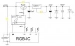
bc3376-2.jpg


Dots:
Red = bc337 NPN transistor
Orange = LM317 voltage regulator (DDL style)
Yellow = CNY17-3 opto isolator
Green = RGB LED IC, common anode (+).
Blue = 1N4004 diode
Violet = 1 kohm resistor
Pink = 470 ohm resistor (if the rgb-circuit run from 4-6V and 20-40mA)
Brown = laser diode
Gray = +12V


Squares:
Orange = threshold resistor (around 50 ohm, 2W for green, 560 ohm 1/4W for red/violet). Some experimenting needed.
Yellow = 10µF 16V electrolytic capacitor. Not needed
Green = max current resistor for laser diode (use ohm's law to find your value)
Blue = 100 ohm pot
Violet = 47µF 16V electrolytic capacitor
Pink = 100nF ceramic capacitor Not needed on the "BigClive-kit" as it comes with its own filter. The laser diode will however.
Brown = 10 kohm pot (sensitivity adjust)
Gray = ground (negative)


The "BigClive-kit" runs from 12V, if you use that you don't need the 470 ohm resistor in series with it.
 
Last edited:
Joined
Jan 12, 2008
Messages
3,290
Points
83
I wouldn't waste my money on that. An LM317 with a pot does just that, all you need to have control over is the current. Use an old ATX power supply and you'll have mains power as well.
 
Joined
Feb 11, 2009
Messages
505
Points
0
I wouldn't waste my money on that. An LM317 with a pot does just that, all you need to have control over is the current. Use an old ATX power supply and you'll have mains power as well.

But how are you able to control the amount of volts going into each diode by using an ATX power supply. In the DDL circuits we build, the 317 and pot control the amperage, right? I don't want to overvolt my diode :)!

-Jakob
 
Joined
Jan 12, 2008
Messages
3,290
Points
83
In a DDL style setup the LM317 will automaticly raise and lower the voltage to maintain the current its set at. When you set it to a higher current it will raise the voltage until it reaches the desired current and stay there, even if the diode heats up or cools down.

Just don't think about it. Voltage control is for lightbulbs.
 
Joined
Feb 11, 2009
Messages
505
Points
0
In a DDL style setup the LM317 will automaticly raise and lower the voltage to maintain the current its set at. When you set it to a higher current it will raise the voltage until it reaches the desired current and stay there, even if the diode heats up or cools down.

Just don't think about it. Voltage control is for lightbulbs.

So if I were to use an DDL to run a red LOC with 10V going into the driver, it would automatically adjust to around 3V output? Or would it give the diode too much voltage?

-Jakob
 
Joined
Jan 12, 2008
Messages
3,290
Points
83
Correct. But you must never disconnect the diode from the driver and reconnect it, or it will take the full 10V and fry. This is old news btw, you should of known this by now.
 
Joined
Feb 11, 2009
Messages
505
Points
0
Correct. But you must never disconnect the diode from the driver and reconnect it, or it will take the full 10V and fry. This is old news btw, you should of known this by now.
I had no idea. I just always assumed you had to put it the right amount of volts to get out the right amount. Sorry :cryyy:

-Jakob
 
Joined
Feb 1, 2008
Messages
2,894
Points
0
the lm317 has the official title as an "adjustable voltage regulator", but we here at LPF are accustomed to using the ic as a current regulator. FML is correct though, the voltage is nothing to worry about while using the lm317 as long as you give it some proper input voltage.


Top