

Hi,
I've been working on this project for a while, several months+ and it's time to start cutting some metal this week.
The laser head contains the 3 lasers, planned to be 400mw of red, 150mw of green and a M140 for blue which will be set about 500mw or so to give the best colour balance.
I may have to crop the beams to ensure a decent overlap of the RGB, but also have a idea that may help reduce the width of the red beam to get a good RGB overlap
I've also working prototype microprocessor that with control the laser brightness using PWM, so I'll easy get 32 decrete visible steps on each laser giving 32,000 "colours". - never see this many by eye, but its good bragging rights")
The design 'twist' is that I'll have a LCD to display and control the modes.
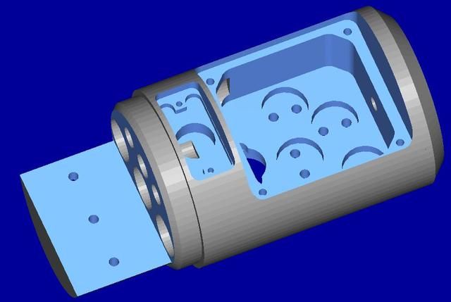
As seen in the 3d model, the optics bay has 4 recesses for 2 dichroics and 2 mirrors. The cover plate that bolts over the bay will have the lcd recessed into it.
Small holes above the 3 laser module holes are for the lcd cabling to the u.p. board.
The small recess in front of this will have one of those micro 5 way joystick switches to slect the modes from the LCD menu.
the half moon shape is the driver tray / heat sink - I intend to fix the drivers to a small piece of ali and bolt this to the driver tray via 3 M2.5 screws. This will alow for easy servicing and removal of the lasers.
A threaded tapered cone will connect the laser head to the battery tube and enclose the drivers and u.p board.
Underside of the laser head will have a key switch, this mounted on a plate to cover up all the bolt holes needed to hold the mirror / dichroic mounts in place.
The u.p will be fixed to the rear face of the driver tray
The head is 48.5mm dia x 68.0mm (excluding the driver tray).
..............well that's the plan, I'll update the thread as I make the parts / agony of failure / extacy of sucess etc.
ATB
MM.
14th Sept.
Made some progress today:-
Machined the mirror and dichoic mounts, they are 10mm tall x 8mm wide.
The small square the mirror fixes to is 7.0 x 8.0mm and has 4 M2 adjustment screws with 1 grub screw that acts as a pivot.
the mirror mount is machined on the end of a 12mm bar, both the mount and square adjuster thingimabob in one go.
The are left joined by a wafer thin strip which is cut off with a scalpel and a small fine to remove the burr.
The M2 holes need tapping and bolting together - the hard work done on these and I'm happy.
Photos show the setup and AA battery for scale.
Also machined most of the laser head, I'll post a photo when its finished.


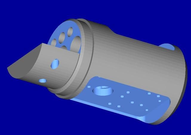
Update 15th Sept:-
Photo of the head, just the module holes and wire access holes to machine in the end above the driver tray and skim the front face where the beam will exit......oh and tap the M2, M2.5 and M3 holes and it will be finished.
Now working on the underside cover that the key switch will me mounted to.
ATB
MM

Bit more progress - more holes !!!!!
Centre hole at top for joystick wires
top two outside holes for LCD wires
3 large holes - no prizes for guessing
2 holes between 12mm module holes are for the cable from key the switch.

Made the joystick insert. This clamps the pcb in the recess, a small flat button will press onto the joystick to cover the central hole.

Completed the design of the next part, the underside cover which will hold the key switch and also cover up all the holes and bolts that hold the mirror mounts in place.
The large hole in the centre is for the switch and is M12x1.0 - overall length of the cover is 57.0 x 34 wide.
Should be interesting if it ends up looking anything like the model !

Bit of progress while waiting to sneak some machine time....
Drafted the PCB. Uses a ATMega328, connectors are, PWM to drivers, SPI to LCD, Joystick, in circuit programming header etc, based on my breadboard hacked version.
2 holes at the bottom are for fixing the board to the back of the driver tray.
The transistor lookng device (above the right side mounting hole) is a temp sensor that will be burried in the heat sink so that the running temp can be displayed on the LCD, this will also give the posibility of automatically lowering the power of the lasers if the temp gets to high.
I've also added a potential devider to measure the battery voltage - haven't tested this on the bread board, but should work.
The silk screen needs a bit of tidying up.
Looks good so far, but will it work? Only one way to find out

Assembled one of the mirror mounts today - incy wincy little things.
The mount pivots on the central screw and can be adjusted in / out to give Z adjustment.
X Y adj using the 4 outside screws - looks like it will work.

Made the key switch cover today - came out great.
I've just got to tap the hole M12x1.0 for the switch and it's complete.
.....onwards to the LCD cover now.....


ATB
MM
Software Sunday
I used a different LCD to develop some of the program routines so spent a few hours today converting it to run on the smaller LCD that will be fitted in the laser head.
1. Power set is a global power "factor" so I'll be able to run the laser at say 10% while setting up and then crank it up for pointing about.
2. Menu to select Pre-Programmed Colours
3. Set and tune the PPC colours - (red through to Violet in 9 or 10 steps)
4. Auto Chase the PPC's
5. Fade through the full RGB range
6. Manual colour mixer.
8. Beams
9. Temp and bat voltage display
10 Spare.
etc.
ATB
MM


Completed the design for the LCD cover.
Hope to get this done this week.
ATB MM.

Another piece to the puzzle.
The PCBs arrived today, a day early.
Hummmm, its didn't look that small on my screen !
Time to get out my glasses, magnifying glass and the hot pointy thing and stick the bits and bobs on the PCB.


ATB
MM.
Tested some of the PCB, it actually works !!!!.
Those SMT caps and resistors are a pain
To start with I tested a single LED, and then when I knew the 'brain' was working, connected up the LCD, that works too.
So just the RGB PWM outputs, heatsink temperature and battery voltage inputs to test and it's good to go.

ATB
MM.
Finally got the LCD cover machined today - took all day by the time I'd made the fixture, sorted a few errors, tuned the program etc + good knows how many evenings to get the CAM programmed. - I won't show the two 'scrappers' I made before I got this good one
First photo shows the machining setup, furthest position the blank is held in a vice and the underside recess is machined that holds the LCD.
Mid station is for drilling and counterboring the fixing holes. (its clamped jusing just 2 M8 bolts.
Third station closest, is where the part is bolted down using the fixing positions and the final surfaces machined to complete the part.
Soon be able to start putting this thing together......
ATB
MM


Sketch of the Laser assembly.
ATB
MM

I think all the main parts are complete, this week, my brother (Mr Lathe) knocked out the battery tube, end cap and microprocessor housing.
I've shown a 2D maglite for size comparison, the RGB laser is smaller in diameter and about 10mm longer (photos make it look longer than it actually is.
One more parts to make is the driver heat sink mount. I've this designed and will try to machine this next week (got to do some 'real work 'first though !!!).
ATB
MM


Done the driver mount.
The 3 drivers are glues to the mount with thermal adhesive.
2 drivers mount vertically and the red driver lays flat to miss the LCD connector.
The main FET is stuck against the vertical wall and the little post is for sinking the resistors, hopefully I got it right and there is about a 1/2mm gap between the resistor and mount to prevent a short, I'll drop a bit of thermal plaster in the gap to transfer some heat .
The mount and drivers are bolted to the driver shelf of the main head, to make it easier to service the drivers.
The hole is to access the driver current adjust pot.

ATB
MM
Hi All,
I got the driver mount / heat sink thingie completed today.
This will be bolted to the main body driver tray once the wires are soldered and current set.
The vertical upstands are to sink the main FET and resistors, I'll use heat sink "plaster" to fix the drivers in place.
larger hole ot to access the current control pot and the 3 smaller holes are M2.5 to attach it to the main body driver tray.
Got to be getting close to doing the assembly at last !
ATB
MM


Hi,
Powered up the drivers, looking good.
Got some work to do with that fat red beam ! but will get it all togeter first and try a few ideas after.
Red 500mW, Green 130mw, Blue 1.1W, measured at a total of 1.75W
ATB
MM

Started the final assembly:-
Lasers wired to the driver and installed.
Joystick wired to the uP board.
PWM / TTL signals from uP to drivers soldered.
....waiting for silicone wire to be delivered so I can finish off the main power and LCD wiring.
I machined the front of the laser housing . The curved slot will be for a manual shutter.


ATB
MM
Cutting jig for slicing the dichro's.
Bit heath-robinson but worked a treat.
Dremel with a diamond disc mounted in a small bench vice.
Dicro mounted on the carriage of a small linear rail.
......right, where is the epoxy.
ATB
MM

Epoxy has set
Quick few shots of the optics and the beam profile. and a short video of it cyling through RGB to give red green blue yellow purple. (not mixing yet).
Target is a sheet of A4 white paper, power is about 10%
Green and blue overlap is fairly good, the red as expected is W I D E.
There is a nice white dot in the centre, but as expected massive red wings, so onto getting the correction optics sorted.
ATB
MM


Video- beam onto the back of a piece of white A4 paper to diffuse the beam to see the colours.
And another....
Anodising done:-

Not the most exciting part, but still an important part - the battery contact.
The small brass stud is soldered to the main power wire that is connected to the PCB, this is bolted to the back of the spring contact pcb during assembly.
I recon, tomorrow I'll be able to power up using the batteries for the first time -

POWER UP !!!!!!!!!!!!!
A few quick photos of the RGB handheld laser powered up...all I can say is PHOAR !!!!
Photos are taken inside, my PC monitor is shown in the bottom of shot for scale.
Power was set at 12% hence the beam showing dots due to the 90% off time.
I'll take more outside beam shots / video on a foggy night and show what the "special function" can do.
My little compact camera doesn't do the colours justice - amazing in person.
ATB
MM


I've been working on this project for a while, several months+ and it's time to start cutting some metal this week.
The laser head contains the 3 lasers, planned to be 400mw of red, 150mw of green and a M140 for blue which will be set about 500mw or so to give the best colour balance.
I may have to crop the beams to ensure a decent overlap of the RGB, but also have a idea that may help reduce the width of the red beam to get a good RGB overlap
I've also working prototype microprocessor that with control the laser brightness using PWM, so I'll easy get 32 decrete visible steps on each laser giving 32,000 "colours". - never see this many by eye, but its good bragging rights
The design 'twist' is that I'll have a LCD to display and control the modes.
As seen in the 3d model, the optics bay has 4 recesses for 2 dichroics and 2 mirrors. The cover plate that bolts over the bay will have the lcd recessed into it.
Small holes above the 3 laser module holes are for the lcd cabling to the u.p. board.
The small recess in front of this will have one of those micro 5 way joystick switches to slect the modes from the LCD menu.
the half moon shape is the driver tray / heat sink - I intend to fix the drivers to a small piece of ali and bolt this to the driver tray via 3 M2.5 screws. This will alow for easy servicing and removal of the lasers.
A threaded tapered cone will connect the laser head to the battery tube and enclose the drivers and u.p board.
Underside of the laser head will have a key switch, this mounted on a plate to cover up all the bolt holes needed to hold the mirror / dichroic mounts in place.
The u.p will be fixed to the rear face of the driver tray
The head is 48.5mm dia x 68.0mm (excluding the driver tray).
..............well that's the plan, I'll update the thread as I make the parts / agony of failure / extacy of sucess etc.
ATB
MM.
14th Sept.
Made some progress today:-
Machined the mirror and dichoic mounts, they are 10mm tall x 8mm wide.
The small square the mirror fixes to is 7.0 x 8.0mm and has 4 M2 adjustment screws with 1 grub screw that acts as a pivot.
the mirror mount is machined on the end of a 12mm bar, both the mount and square adjuster thingimabob in one go.
The are left joined by a wafer thin strip which is cut off with a scalpel and a small fine to remove the burr.
The M2 holes need tapping and bolting together - the hard work done on these and I'm happy.
Photos show the setup and AA battery for scale.
Also machined most of the laser head, I'll post a photo when its finished.
Update 15th Sept:-
Photo of the head, just the module holes and wire access holes to machine in the end above the driver tray and skim the front face where the beam will exit......oh and tap the M2, M2.5 and M3 holes and it will be finished.
Now working on the underside cover that the key switch will me mounted to.
ATB
MM
Bit more progress - more holes !!!!!
Centre hole at top for joystick wires
top two outside holes for LCD wires
3 large holes - no prizes for guessing
2 holes between 12mm module holes are for the cable from key the switch.
Made the joystick insert. This clamps the pcb in the recess, a small flat button will press onto the joystick to cover the central hole.
Completed the design of the next part, the underside cover which will hold the key switch and also cover up all the holes and bolts that hold the mirror mounts in place.
The large hole in the centre is for the switch and is M12x1.0 - overall length of the cover is 57.0 x 34 wide.
Should be interesting if it ends up looking anything like the model !
Bit of progress while waiting to sneak some machine time....
Drafted the PCB. Uses a ATMega328, connectors are, PWM to drivers, SPI to LCD, Joystick, in circuit programming header etc, based on my breadboard hacked version.
2 holes at the bottom are for fixing the board to the back of the driver tray.
The transistor lookng device (above the right side mounting hole) is a temp sensor that will be burried in the heat sink so that the running temp can be displayed on the LCD, this will also give the posibility of automatically lowering the power of the lasers if the temp gets to high.
I've also added a potential devider to measure the battery voltage - haven't tested this on the bread board, but should work.
The silk screen needs a bit of tidying up.
Looks good so far, but will it work? Only one way to find out
Assembled one of the mirror mounts today - incy wincy little things.
The mount pivots on the central screw and can be adjusted in / out to give Z adjustment.
X Y adj using the 4 outside screws - looks like it will work.
Made the key switch cover today - came out great.
I've just got to tap the hole M12x1.0 for the switch and it's complete.
.....onwards to the LCD cover now.....
ATB
MM
Software Sunday
I used a different LCD to develop some of the program routines so spent a few hours today converting it to run on the smaller LCD that will be fitted in the laser head.
1. Power set is a global power "factor" so I'll be able to run the laser at say 10% while setting up and then crank it up for pointing about.
2. Menu to select Pre-Programmed Colours
3. Set and tune the PPC colours - (red through to Violet in 9 or 10 steps)
4. Auto Chase the PPC's
5. Fade through the full RGB range
6. Manual colour mixer.
8. Beams
9. Temp and bat voltage display
10 Spare.
etc.
ATB
MM
Completed the design for the LCD cover.
Hope to get this done this week.
ATB MM.
Another piece to the puzzle.
The PCBs arrived today, a day early.
Hummmm, its didn't look that small on my screen !
Time to get out my glasses, magnifying glass and the hot pointy thing and stick the bits and bobs on the PCB.
ATB
MM.
Tested some of the PCB, it actually works !!!!.
Those SMT caps and resistors are a pain
To start with I tested a single LED, and then when I knew the 'brain' was working, connected up the LCD, that works too.
So just the RGB PWM outputs, heatsink temperature and battery voltage inputs to test and it's good to go.
ATB
MM.
Finally got the LCD cover machined today - took all day by the time I'd made the fixture, sorted a few errors, tuned the program etc + good knows how many evenings to get the CAM programmed. - I won't show the two 'scrappers' I made before I got this good one
First photo shows the machining setup, furthest position the blank is held in a vice and the underside recess is machined that holds the LCD.
Mid station is for drilling and counterboring the fixing holes. (its clamped jusing just 2 M8 bolts.
Third station closest, is where the part is bolted down using the fixing positions and the final surfaces machined to complete the part.
Soon be able to start putting this thing together......
ATB
MM
Sketch of the Laser assembly.
ATB
MM
I think all the main parts are complete, this week, my brother (Mr Lathe) knocked out the battery tube, end cap and microprocessor housing.
I've shown a 2D maglite for size comparison, the RGB laser is smaller in diameter and about 10mm longer (photos make it look longer than it actually is.
One more parts to make is the driver heat sink mount. I've this designed and will try to machine this next week (got to do some 'real work 'first though !!!).
ATB
MM
Done the driver mount.
The 3 drivers are glues to the mount with thermal adhesive.
2 drivers mount vertically and the red driver lays flat to miss the LCD connector.
The main FET is stuck against the vertical wall and the little post is for sinking the resistors, hopefully I got it right and there is about a 1/2mm gap between the resistor and mount to prevent a short, I'll drop a bit of thermal plaster in the gap to transfer some heat .
The mount and drivers are bolted to the driver shelf of the main head, to make it easier to service the drivers.
The hole is to access the driver current adjust pot.
ATB
MM
Hi All,
I got the driver mount / heat sink thingie completed today.
This will be bolted to the main body driver tray once the wires are soldered and current set.
The vertical upstands are to sink the main FET and resistors, I'll use heat sink "plaster" to fix the drivers in place.
larger hole ot to access the current control pot and the 3 smaller holes are M2.5 to attach it to the main body driver tray.
Got to be getting close to doing the assembly at last !
ATB
MM
Hi,
Powered up the drivers, looking good.
Got some work to do with that fat red beam ! but will get it all togeter first and try a few ideas after.
Red 500mW, Green 130mw, Blue 1.1W, measured at a total of 1.75W
ATB
MM
Started the final assembly:-
Lasers wired to the driver and installed.
Joystick wired to the uP board.
PWM / TTL signals from uP to drivers soldered.
....waiting for silicone wire to be delivered so I can finish off the main power and LCD wiring.
I machined the front of the laser housing . The curved slot will be for a manual shutter.
ATB
MM
Cutting jig for slicing the dichro's.
Bit heath-robinson but worked a treat.
Dremel with a diamond disc mounted in a small bench vice.
Dicro mounted on the carriage of a small linear rail.
......right, where is the epoxy.
ATB
MM
Epoxy has set
Quick few shots of the optics and the beam profile. and a short video of it cyling through RGB to give red green blue yellow purple. (not mixing yet).
Target is a sheet of A4 white paper, power is about 10%
Green and blue overlap is fairly good, the red as expected is W I D E.
There is a nice white dot in the centre, but as expected massive red wings, so onto getting the correction optics sorted.
ATB
MM
Video- beam onto the back of a piece of white A4 paper to diffuse the beam to see the colours.
And another....
Anodising done:-
Not the most exciting part, but still an important part - the battery contact.
The small brass stud is soldered to the main power wire that is connected to the PCB, this is bolted to the back of the spring contact pcb during assembly.
I recon, tomorrow I'll be able to power up using the batteries for the first time -
POWER UP !!!!!!!!!!!!!
A few quick photos of the RGB handheld laser powered up...all I can say is PHOAR !!!!
Photos are taken inside, my PC monitor is shown in the bottom of shot for scale.
Power was set at 12% hence the beam showing dots due to the 90% off time.
I'll take more outside beam shots / video on a foggy night and show what the "special function" can do.
My little compact camera doesn't do the colours justice - amazing in person.
ATB
MM
Last edited:


")
 ( and im considering a redesign..what is the OD on that head piece?