Welcome to Laser Pointer Forums - discuss green laser pointers, blue laser pointers, and all types of lasers
How to Register on LPF | LPF Donations

Navigation
Install the app
How to install the app on iOS
Follow along with the video below to see how to install our site as a web app on your home screen.
Note: This feature may not be available in some browsers.
More options
You are using an out of date browser. It may not display this or other websites correctly.
You should upgrade or use an alternative browser.
You should upgrade or use an alternative browser.
Red DIY DVD laser burner.
- Thread starter Kenom
- Start date


- Joined
- Jan 7, 2007
- Messages
- 6,336
- Points
- 83
I forgot to add, this is with the 1 watt Luxon LED as supplied running at about 800 mA. The frequency will likely remain stable, only the pulse width will change under changing conditions. It still shows power supply output under load.
Mike
Mike
Thanks Kenom, and others who helped me with my problem,
I now know what I was doing wrong. The remedy on the other hand is a little out of my skill levels at the moment... I've decided to purchase a metal dorcy laser from Angel, as obviously you people know what your doing...(and not fumbling their way through it, like myself... :") )
)
just a further question, I mentioned my problems to a guy at work who used to do electronics, he mentioned that for delicate electronics he used solder paste and a modified hot air gun... would that be suitable for this project?
I now know what I was doing wrong. The remedy on the other hand is a little out of my skill levels at the moment... I've decided to purchase a metal dorcy laser from Angel, as obviously you people know what your doing...(and not fumbling their way through it, like myself... :
)just a further question, I mentioned my problems to a guy at work who used to do electronics, he mentioned that for delicate electronics he used solder paste and a modified hot air gun... would that be suitable for this project?
Nah, nothing here should need solder paste and a hot air gun (maybe just for mounting tiny surface-mount components). Just tin the leads first, and minimize the time that you're applying the heat.
Ideally you could use a temperature controlled soldering iron, but it really shouldn't be necessary. If you haven't done much soldering, practice on some other things first.
Now, as for the pulse frequency from the Dorcy driver...
I also expected to just see the pulse width change, but clear as day on my scope I saw a huge frequency shift as the load increased. Try it with a lower load (like a couple of regular LEDs in series) and see if you don't get the same thing.
[Not that the frequency is all that important, just a curiosity really. But it makes me want to see a datasheet on that driver.]
I read posts suggesting current limiting a Dorcy driver through a series resistor, other posts suggesting current limiting a 7135 through a parallel resistor to siphon off about 100ma.
Is there a consensus yet as to whether it is better to use a Dorcy or a 7135 if you have it laying around (or a 317T driver?)
Is there a consensus yet as to whether it is better to use a Dorcy or a 7135 if you have it laying around (or a 317T driver?)
Gazoo
0
- Joined
- Jun 9, 2007
- Messages
- 3,206
- Points
- 38
My thoughts are to use the 317 for labbys. They also work very well for controlling the current to the laser diode and the TEC. And as we know the circuit requires a minimum of 6 volts.
For the 7135 vs. the Dorcy, I would think it is a matter of what you want to end up with. The 7135 would be perfect for the Dorcy Metal Gear since the flashlight takes 3 AAA batteries. I have no experience with the Dorcy JR. But my preference for a portable would be the 7135 for all the reasons I stated in my review of it.
For the 7135 vs. the Dorcy, I would think it is a matter of what you want to end up with. The 7135 would be perfect for the Dorcy Metal Gear since the flashlight takes 3 AAA batteries. I have no experience with the Dorcy JR. But my preference for a portable would be the 7135 for all the reasons I stated in my review of it.
I notice DX has these modules incorporating 7135's as well. The 5-mode switchables. One mode is 20% current output which would limit LED current to around 200ma.
http://www.dealextreme.com/details.dx/sku.6190
That current range sounds perfectly safe for the GB diode in cw mode.
One would have to play with this module a fair amount to make sure they understood the switching mechanism however to avoid turning on one day and frying the diode with a full 1050ma.
- Joined
- Sep 22, 2007
- Messages
- 169
- Points
- 18
I also have the high pitched whine coming from my Dorcy and i don't have a cap on it, so i don't think it is that :-/ oh well, i can deal with it cause this thing ROCKS ;D
My dorcy ran the Luxeon led at 350ma and i am using one 10 ohm resistor on my diode and am getting about 190 ma. This seems about right for me, it easily lights matches, etc. and is plenty bright
Shilood said:I read posts suggesting current limiting a Dorcy driver through a series resistor, other posts suggesting current limiting a 7135 through a parallel resistor to siphon off about 100ma.
Is there a consensus yet as to whether it is better to use a Dorcy or a 7135 if you have it laying around (or a 317T driver?)
My dorcy ran the Luxeon led at 350ma and i am using one 10 ohm resistor on my diode and am getting about 190 ma. This seems about right for me, it easily lights matches, etc. and is plenty bright
- Joined
- Aug 17, 2007
- Messages
- 238
- Points
- 0
jayhawker08 said:I also have the high pitched whine coming from my Dorcy and i don't have a cap on it, so i don't think it is that :-/ oh well, i can deal with it cause this thing ROCKS ;D
[quote author=Shilood link=1181635652/270#276 date=1192738617]I read posts suggesting current limiting a Dorcy driver through a series resistor, other posts suggesting current limiting a 7135 through a parallel resistor to siphon off about 100ma.
Is there a consensus yet as to whether it is better to use a Dorcy or
a 7135 if you have it laying around (or a 317T driver?)
My dorcy ran the Luxeon led at 350ma and i am using one 10 ohm resistor on my diode and am getting about 190 ma. This seems about right for me, it easily lights matches, etc. and is plenty bright
[/quote]Jay:
How long have you had this thing operating with the 10 ohm resistor? Did you try different values before the 10 ohm? Thanks.
- Joined
- Sep 6, 2007
- Messages
- 51
- Points
- 0
VICTORY!!! I made my Dorcy Mini Burner! ;D Thanks for the instructions, Ken!
For a heatsink, I filled the head (quite poorly) with solder - lots of time and mess, with lots of airspace in the solder, though it's working quite well. To do it, I wrapped the end of an Aixiz module in aluminum foil, put foil down on the surface I was working on, put the top of the Dorcy front-end down with the wrapped module in the middle, and melted a lot of solder into it. Then I smeared the inside of the solder and the module with thermal grease before fitting them together. It was a pain and it's really ugly, but it's working great.
For circuit protection, it soldered a tantalum 1µf 16V capacitor to the leads of the LD. I also put in a 4.7 ohm resistor in by cutting the spring between the two circuit boards in half, putting a layer of insulation in between the halves, and put the resistor in touching both sides of the spring.
All in all, it's a pretty awesome burner. When I hit the sweet spot in the beam, dark stuff starts smoking like crazy! WOOHOO[smiley=vrolijk_26.gif]
Kenom
0
- Joined
- May 4, 2007
- Messages
- 5,628
- Points
- 63
Excellent glad to hear you gotter working. I've actually had to change the way I modify this thing since the current coming from the driver is no longer regulated to 350ma. 390ma is instant death to diode and I blew 6 of them before I figured that it wasn't me but the circuit. Here are pictures of what I have to do in order to get my Dorcy to not blow diodes instantly.
Now mind you this isn't as "pretty" as the previous mod but it does do the trick. I'm using 4 10-ohm resistors since I can't buy 5-ohm resistors locally. You can just use one 2.5 ohm resistor and do the same thing. Essentially the Resistors becomes our negative connection to the battery body. Here is the battery body

We then need to make our Positive fit down into the hole for the positive spring. This used to be done with the cone and spring assembly but since I'm having to add resistors and capacitors and such I no longer have room to use the "light board assembly" Now this is NOT the driver for this light. The driver is below the black plastic in the battery portion of the flashlight. So to get the postive I cut a section off the spring and soldered it to a resistor wire (without the resistor) and set it to fit inside the positive hole!.


You can notice with it sitting inside the head that the negative (resistor ends) comes almost in contact with the barrel and the positive is centered. When I screw the cap on both the positive and negative connections are made and she works! You will have to mess with the length of the spring a bit. I ended up soldering and desoldering the spring probably 20 times one night.
Now mind you this isn't as "pretty" as the previous mod but it does do the trick. I'm using 4 10-ohm resistors since I can't buy 5-ohm resistors locally. You can just use one 2.5 ohm resistor and do the same thing. Essentially the Resistors becomes our negative connection to the battery body. Here is the battery body
We then need to make our Positive fit down into the hole for the positive spring. This used to be done with the cone and spring assembly but since I'm having to add resistors and capacitors and such I no longer have room to use the "light board assembly" Now this is NOT the driver for this light. The driver is below the black plastic in the battery portion of the flashlight. So to get the postive I cut a section off the spring and soldered it to a resistor wire (without the resistor) and set it to fit inside the positive hole!.
You can notice with it sitting inside the head that the negative (resistor ends) comes almost in contact with the barrel and the positive is centered. When I screw the cap on both the positive and negative connections are made and she works! You will have to mess with the length of the spring a bit. I ended up soldering and desoldering the spring probably 20 times one night.
- Joined
- Sep 6, 2007
- Messages
- 51
- Points
- 0
You're putting the resistors on the negative? Hmm, based on Daedal's circuit I put mine in the positive. I wish I had some of those heatsinks you have, that would make everything a lot easier. My solder does well, but it's ugly as sin, let me tell ya. The hardest part for me was to get the capacitor in there. I broke the positive and photodiode pins off the first diode I tried with because it was too big (a tiny 1µf tantalum too big... crazy.) It was still a bit too long on the second try, but luckily I was able to move stuff around and get it set up right. Now it's working pretty well, instantly smoking black stuff and popping dark balloons when I hit the right point in the beam. I love it, thanks Ken!
- Joined
- Aug 17, 2007
- Messages
- 238
- Points
- 0
Nice work Ken! great pics. Good to know this arrangement works for you.
I've just received a new diode from Greg so this will be my second attempt. I've got the cap and resistors and I'll also be trying that aluminum shaft collar heat sink.
We'll see what happens.
I've just received a new diode from Greg so this will be my second attempt. I've got the cap and resistors and I'll also be trying that aluminum shaft collar heat sink.
We'll see what happens.
Kenom
0
- Joined
- May 4, 2007
- Messages
- 5,628
- Points
- 63
Boy I hate this question. Nothing personal we've all thought it. but unless you've got x-ray glasses to see what kind of diode it is there really is no way to know until you've destroyed it. Since it is a name brand and I'm assuming a higher speed drive you should be fine. But I just got done tearing into 13 dvd-rw's and I only got 2 normal laser diodes outta the lot! Obviously it's too late to put stuff back together and get it workin again if you've taken the diode out! Sometimes you can see by looking at teh sled assembly if it's a normal diode without taking anything off! Let us know how it goes
- Joined
- Aug 17, 2007
- Messages
- 238
- Points
- 0
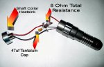
OK Guys. I finally got this thing to work!!! 
Before packaging everything properly, I wanted to see if it would lase as I blew the first diode instantly due to excessive current. The setup you see here is quick and dirty but it does work. Someone said that they used 10 Ohms to limit current. Ken, I think you mentioned 5. I thought I'd try something in between and used 8 Ohms. I'll see what it's drawing and then adjust. I only tested it on a couple of green (UN Sharpied) balloons and it popped them almost instantly so I think I'm in the ballpark.
Do you think 8 Ohms is a little too much?
Attachments