Welcome to Laser Pointer Forums - discuss green laser pointers, blue laser pointers, and all types of lasers
Buy Site Supporter Role (remove some ads) | LPF Donations
Links below open in new window
FrozenGate by Avery

Navigation
Install the app
How to install the app on iOS
Follow along with the video below to see how to install our site as a web app on your home screen.
Note: This feature may not be available in some browsers.
More options

You are using an out of date browser. It may not display this or other websites correctly.
You should upgrade or use an alternative browser.
You should upgrade or use an alternative browser.
PT-54 wiring.
- Thread starter bhwollen
- Start date


- Joined
- Aug 30, 2008
- Messages
- 6,891
- Points
- 83

jayrob
0
- Joined
- Sep 21, 2007
- Messages
- 9,862
- Points
- 113
You can see my connections in the picture of my build here:
http://laserpointerforums.com/f42/9-amp-pt-54-phlatlight-maglite-mod-64054.html
Remember that the entire base of the emitter is 'case positive'. So you need to isolate it in a case negative build...
See here as well for a drawing:
http://laserpointerforums.com/f42/phlatlight-12w-red-led-flashlight-61010.html
Edit: Moh beat me to it...
Last edited:
- Joined
- Aug 30, 2008
- Messages
- 6,891
- Points
- 83
for the + i soldered mine to that higher point on a little metal tab cause it was already pre tinned and the solder stuck better there.

- Joined
- Dec 23, 2008
- Messages
- 3,948
- Points
- 63
jays is focusable. if you look at his heat sink, the post that the led is on is to let be focusable.
michael.
michael.
jayrob
0
- Joined
- Sep 21, 2007
- Messages
- 9,862
- Points
- 113
thanks guys!
I was looking at your thread jay, but couldn't find how to wire it.
Also jay, how did you make it focusable?
Oh...
Well I thought you could just tell from looking at the red and black wires soldered on:

This picture also shows how it can focus with a Maglite build...
The reflector is connected to the head of the host, which is threaded onto the body. So you can adjust the position as you turn the head...
")
Last edited:
- Joined
- Oct 26, 2007
- Messages
- 5,438
- Points
- 83
(NOTE: PLEASE SEE POST BELOW FOR CORRECT INFORMATION. THIS POST IS ERRONEOUS)
Here is the datasheet (working link, no pin-out unfortunately).
Just for reference so people don't need to fish around, here's the pin-out (pin 1 is on the left if the connector is on top; on the bottom if oriented as in Mohrenberg's photo):
Pins 1 - 3: +2.7V (anode)
Pins 4 - 6: GND (cathode)
Pins 7 - 8: Thermistor inputs
The thermistor is a NCP15XH103J03RC, a 10k thermistor with a B-constant of 3380. You can use that to, for example, adjust the peltier on the heatsink the board comes with to keep the board under the 80C maximum temperature.
Last edited:
jcranmer
0
- Joined
- Mar 23, 2011
- Messages
- 2,095
- Points
- 63
I'm confused, I found a data sheet earlier that seems to indicate things a bit backwards then this. The drawing linked matches what I found though.
Pins 1 -2: Thermistor
Pins 3-5: -
Pins 6-8: +
Pin 1 as I understand it, is at the top of the pic Moh posted and Pin 8 is at the bottom.
Am I just confused here? I'd like to triple check this before I left the smoke out it.
This of course only matters if you are going to use the wiring from the projector and not soldering directly to the PCB.
Here is the datasheet (working link, no pin-out unfortunately).
Just for reference so people don't need to fish around, here's the pin-out (pin 1 is on the left if the connector is on top; on the bottom if oriented as in Mohrenberg's photo):
Pins 1 - 3: +2.7V (anode)
Pins 4 - 6: GND (cathode)
Pins 7 - 8: Thermistor inputs
The thermistor is a NCP15XH103J03RC, a 10k thermistor with a B-constant of 3380. You can use that to, for example, adjust the peltier on the heatsink the board comes with to keep the board under the 80C maximum temperature.
- Joined
- Oct 26, 2007
- Messages
- 5,438
- Points
- 83
Well, the socket labeling on the projector's power board and the pin labeling in the top photo of the datasheet show pin-1 on the bottom if the socket is oriented on the left, when looking at the board from the top. They may have screwed that up though, because similar connectors on the power board have the pins starting from the other end. (NOTE: see below)
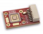
Just to be perfectly unambiguous no matter what the pin numbering, in this photo, the little black rectangle connected to the bottom two pins in the photo below is the thermistor, the middle three pins are Cathode (GND), and the top three pins are Anode (+). Each pin is designed to take only 3A max.

Edit:
According to this revision datasheet (unfortunately some crummy Flash-based one), the correct pin-out is:
Pin 1: Thermistor +
Pin 2: Thermistor -
Pin 3-5: Power -
Pin 6-8: Power +
Where Pin 1 is on the bottom as per the above photo.
Just to be perfectly unambiguous no matter what the pin numbering, in this photo, the little black rectangle connected to the bottom two pins in the photo below is the thermistor, the middle three pins are Cathode (GND), and the top three pins are Anode (+). Each pin is designed to take only 3A max.
Edit:
According to this revision datasheet (unfortunately some crummy Flash-based one), the correct pin-out is:
Pin 1: Thermistor +
Pin 2: Thermistor -
Pin 3-5: Power -
Pin 6-8: Power +
Where Pin 1 is on the bottom as per the above photo.
Attachments
Last edited:
jcranmer
0
- Joined
- Mar 23, 2011
- Messages
- 2,095
- Points
- 63
Well, the socket labeling on the projector's power board and the pin labeling in the top photo of the datasheet show pin-1 on the bottom if the socket is oriented on the left, when looking at the board from the top. They may have screwed that up though, because similar connectors on the power board have the pins starting from the other end. (NOTE: see below)
Just to be perfectly unambiguous no matter what the pin numbering, in this photo, the little black rectangle connected to the bottom two pins in the photo below is the thermistor, the middle three pins are Cathode (GND), and the top three pins are Anode (+). Each pin is designed to take only 3A max.
Edit:
According to this revision datasheet (unfortunately some crummy Flash-based one), the correct pin-out is:
Pin 1: Thermistor +
Pin 2: Thermistor -
Pin 3-5: Power -
Pin 6-8: Power +
Where Pin 1 is on the bottom as per the above photo.
Perfect! Thank you. That photo confirms it. That indeed matches what I had. I was going back though history to see what I was looking at and this is the datasheet I found, HOWEVER I was looking at a CBT-40 and not the PT-54. It looks to be nearly the same device.
http://www.luminus.com/products/datasheets/Luminus_CBT-40_Datasheet.pdf
Again, this isn't the correct datasheet for the PT-54 (I was on my phone and wasn't looking that closely at it on the small screen), but it does have the correct pin-outs listed.