Here is the Full Circuit.
You will need to Calibrate the 1mV Per Amp Signal to the Ammeter with the 25 Turn Pot. The Shunt gives 2.5mV's Per Amp. The Shunts are 0.005 Ohm 4 Watt.
The 3 Pots are 25 Turn Minature PCB mounted Pots. Other resistors are all 0.25 Watt. The 1 uF Capacitor around the Error Amp is NON POLARISED. Don't use a
Polarised Elctrolytic. Use a NP Electrolytic or Ceramic Etc.
Just a quick Warning. NEVER use the Inhibit pin on the Regulator Module when it's in Constant Current mode. This will cause the output from the Current Regulator to go to
MAXIMUM. When you release the Inhibit Pin you will have MAX Output Voltage for a very short time before the Current Regulator drops it. This May damage your LED or laser
Diode etc.
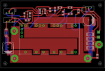
Here is the PCB. Probably not to scale. If you want a Full Scale one PM me and I will send it. This is looking from the Component side.
Component Layout.
NOTE. The Resistor on the UVLO Program pin is missing on the Component layout. But you should be able to tell were it goes.
The Extra Terminal Pads on the +12v and 0v Rails are for Fan's and the Ammeter supplies.
I havnt finished assembling the New PCB with the Current Regulator on the same board yet. I have made the PCB but need some components. I will finish it tomorrow.
I hope others find this a good way to convert these Modules into a Constant Current Module
I Ordered a Sample Yesterday. It got shipped Today. Thanks for the Tip. I have Ordered Heaps of samples from Microchip before. They are very cheap PIC's. I wasn't
expecting these pricey Modules could also be obtained by Sample. Thanks.
Charles


