

- Joined
- Dec 14, 2008
- Messages
- 33
- Points
- 18
Hello LPF,
Here's a project from end of last year, but I finally had some time to do a short post about it. Thought some folks here may be interested in. I hope this is in the correct forum category!
Here's what I'm calling Project 450 - a compact, simple, fully-integrated laser platform. It differs from the usual 'flashlight-style' hosts here, and instead uses a single PCB as the host. This allows mounting of batteries, switches, and has an on-board microcontroller for an array of basic functions. This driver is designed for a maximum constant current drive power of 50W (~4+V at 12A), but in this project, will be running at a more conservative 20W, for about 7W of optical output.
[Update - a small update with Project 450 - the copper block housing was changed to a much higher quality aluminium housing. Batteries were also upgraded to one of the best 16340 cells]

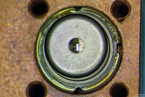
The chosen diode for this build (though capable of driving much more powerful LDs/LEDs) is the 7W NUBM44-V2 450nm blue laser diode, which comes in a TO-5 9mm can package. As of writing, it is currently the most powerful available visible wavelength laser diode.
This project focuses specifically on the design and development of the drive electronics in order to safely drive a constant-current load (such as this diode, or any LED for that matter), and is therefore applicable to all sorts of constant current loads such as LEDs for flashlights.
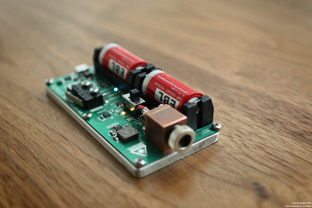
Above - the original Project 450 build with a copper host block - since updated.
I would like to make it abundantly clear that I do not advocate the use of these kinds of laser diodes at these power levels since they are extremely dangerous and any mistake will lead to irreversible eye damage. I hope this project will be a good educational resource; please proceed reading responsibly. Laser goggles are always used (in this case a proper 5+OD for the wavelength googles are always worn whenever operated).
This project has two main aspects - an integrated, compact, single-PCB platform designed to be mounted on an aluminium extrusion as heat-sinking, and a 12A-capable true constant-current synchronous buck converter.
Integrated Platform
The integrated PCB measures exactly 50 x 100mm, making it fairly compact.
Power is supplied via two 16340 batteries in series, which essentially dictates the size of the product. These cells were chosen for their compact size.
In this specific scenario, the maximum diode drive current is only 4.5A at about 4.5+V (~20W), and maximum load current on the cells is about 3A. As a result, the fairly mid-range quality EBL 16340 cells will suffice (with about a ~3A load), though will be upgraded to Vapcell 16340s in the future, which will easily handle over twice the load (7A rated continuous discharge current, tested higher by HKJ) - this will just about handle the maximum 50W capability of this driver.
18350 cells though, will likely be better for those kinds of loads, at the cost of a larger overall size. However the 16340s used successfully handle the full 20W+ load with no issues.
Note that while the drive power is ~20+W, the Lasing output should be about 7W at 4500mA I_fwd. I have no way to measure this, and photonic output values are based on tests conducted by others who have characterized this diode with their test setups.

For convenience, I threw on a charging circuit on board, which allows charging of the cells via micro-USB at 700mA. On board circuitry boosts the 5V from USB to 9V, and charges the 2S battery via a dedicated Li-ion charging IC. For most 16340 cells, this results in a roughly 1 hour charge time from flat.
An Atmel microcontroller handles the entire system for various kinds of events. Here are a few features:
To prevent shorts, holes are milled into the baseplate for through-hole legs to sit in. A kapton sheet was then laser-cut to insulate all other parts, and thermal paste was then applied to the exposed ground copper pads for contact with the baseplate.
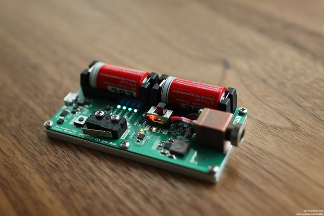
A cutout allows the diode, housed in a solid copper mount, to be attached directly to the baseplate from the bottom. Note the main power switch, the mode push-button switch, and the main toggle switch.
Synchronous Constant-Current Buck Converter
In order to drive the diode safely, a current-regulated driver is required.
There are several that exist today, the most powerful of which commonly available is the BlackBuck 8M Rev 3 by x-wossee. This is a 7-12Vin 1-8A constant current buck driver, using the IR3475 10A integrated SupIRBuck regulator.
While a nice design, I thought I'd go for something with a little more power capability (not that we would need it). My original thought was to go with the TPS548D21, a 40A fully integrated regulator, but that's too excessive (and expensive), so I settled for a sensible 12A design instead, having about 50% more power handling capability than the Blackbuck 8M. We won't need so much power, but I suppose we can adapt this driver for other uses too.

The final design allowed me to layout the buck converter in a very symmetric way, which brings a tear to the eye!
No consideration was made to make the layout as compact as possible, since the PCB had a lot of space. However, the main buck converter portion is very compact, and can likely be made much smaller for use in say flashlights or smaller hosts.
Testing & Results
Testing was initially done with a single Cree XML2 LED to ensure correct operation and proper current regulation, before it was replaced with the laser diode. Frankly, it made a very nice, cute flashlight, so maybe I'll make this into a lamp in the future... I will probably not use this much at all since this is very dangerous, so it will likely have an alternate life as a desktop lamp.")
Power levels were set to be (fairly arbitrarily):
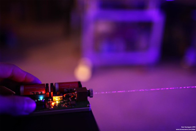
Here's a quick photo of the beamshot. It's slightly difficult to capture how it looks like since the entire room lights up blue, so here's it running at low power (500mW) power setting. Some water droplets were sprayed in the air to make the beam more visible.
The result was as expected and the system runs very well. It easily burns a hole through both sides of a potato chip packet in a second, for example. More to come soon.
Many thanks to the folks here for their work and efforts in characterizing this powerful laser diode, especially DTR. This project builds upon the work they have done.
Hope this was slightly interesting.
Cheers
Here's a project from end of last year, but I finally had some time to do a short post about it. Thought some folks here may be interested in. I hope this is in the correct forum category!
Here's what I'm calling Project 450 - a compact, simple, fully-integrated laser platform. It differs from the usual 'flashlight-style' hosts here, and instead uses a single PCB as the host. This allows mounting of batteries, switches, and has an on-board microcontroller for an array of basic functions. This driver is designed for a maximum constant current drive power of 50W (~4+V at 12A), but in this project, will be running at a more conservative 20W, for about 7W of optical output.
[Update - a small update with Project 450 - the copper block housing was changed to a much higher quality aluminium housing. Batteries were also upgraded to one of the best 16340 cells]
The chosen diode for this build (though capable of driving much more powerful LDs/LEDs) is the 7W NUBM44-V2 450nm blue laser diode, which comes in a TO-5 9mm can package. As of writing, it is currently the most powerful available visible wavelength laser diode.
This project focuses specifically on the design and development of the drive electronics in order to safely drive a constant-current load (such as this diode, or any LED for that matter), and is therefore applicable to all sorts of constant current loads such as LEDs for flashlights.
Above - the original Project 450 build with a copper host block - since updated.
I would like to make it abundantly clear that I do not advocate the use of these kinds of laser diodes at these power levels since they are extremely dangerous and any mistake will lead to irreversible eye damage. I hope this project will be a good educational resource; please proceed reading responsibly. Laser goggles are always used (in this case a proper 5+OD for the wavelength googles are always worn whenever operated).
This project has two main aspects - an integrated, compact, single-PCB platform designed to be mounted on an aluminium extrusion as heat-sinking, and a 12A-capable true constant-current synchronous buck converter.
Integrated Platform
The integrated PCB measures exactly 50 x 100mm, making it fairly compact.
Power is supplied via two 16340 batteries in series, which essentially dictates the size of the product. These cells were chosen for their compact size.
In this specific scenario, the maximum diode drive current is only 4.5A at about 4.5+V (~20W), and maximum load current on the cells is about 3A. As a result, the fairly mid-range quality EBL 16340 cells will suffice (with about a ~3A load), though will be upgraded to Vapcell 16340s in the future, which will easily handle over twice the load (7A rated continuous discharge current, tested higher by HKJ) - this will just about handle the maximum 50W capability of this driver.
18350 cells though, will likely be better for those kinds of loads, at the cost of a larger overall size. However the 16340s used successfully handle the full 20W+ load with no issues.
Note that while the drive power is ~20+W, the Lasing output should be about 7W at 4500mA I_fwd. I have no way to measure this, and photonic output values are based on tests conducted by others who have characterized this diode with their test setups.
For convenience, I threw on a charging circuit on board, which allows charging of the cells via micro-USB at 700mA. On board circuitry boosts the 5V from USB to 9V, and charges the 2S battery via a dedicated Li-ion charging IC. For most 16340 cells, this results in a roughly 1 hour charge time from flat.
An Atmel microcontroller handles the entire system for various kinds of events. Here are a few features:
- Security Safety interlock requiring secret code to be entered via switches before system unlocks, impossible to turn on in a bag
- Constant current control with 4 programmable power modes
- Battery monitoring and low voltage cut-off
- Charge management
- Error codes via a total of 5 colourful LEDs
To prevent shorts, holes are milled into the baseplate for through-hole legs to sit in. A kapton sheet was then laser-cut to insulate all other parts, and thermal paste was then applied to the exposed ground copper pads for contact with the baseplate.
A cutout allows the diode, housed in a solid copper mount, to be attached directly to the baseplate from the bottom. Note the main power switch, the mode push-button switch, and the main toggle switch.
Synchronous Constant-Current Buck Converter
In order to drive the diode safely, a current-regulated driver is required.
There are several that exist today, the most powerful of which commonly available is the BlackBuck 8M Rev 3 by x-wossee. This is a 7-12Vin 1-8A constant current buck driver, using the IR3475 10A integrated SupIRBuck regulator.
While a nice design, I thought I'd go for something with a little more power capability (not that we would need it). My original thought was to go with the TPS548D21, a 40A fully integrated regulator, but that's too excessive (and expensive), so I settled for a sensible 12A design instead, having about 50% more power handling capability than the Blackbuck 8M. We won't need so much power, but I suppose we can adapt this driver for other uses too.
The final design allowed me to layout the buck converter in a very symmetric way, which brings a tear to the eye!
No consideration was made to make the layout as compact as possible, since the PCB had a lot of space. However, the main buck converter portion is very compact, and can likely be made much smaller for use in say flashlights or smaller hosts.
Testing & Results
Testing was initially done with a single Cree XML2 LED to ensure correct operation and proper current regulation, before it was replaced with the laser diode. Frankly, it made a very nice, cute flashlight, so maybe I'll make this into a lamp in the future... I will probably not use this much at all since this is very dangerous, so it will likely have an alternate life as a desktop lamp.
Power levels were set to be (fairly arbitrarily):
- Threshold lasing current
- Bright (0.5W output) at ~600mA
- Powerful (2W output) at ~1.35A
- Turbo (7W output) at ~4.5A
Here's a quick photo of the beamshot. It's slightly difficult to capture how it looks like since the entire room lights up blue, so here's it running at low power (500mW) power setting. Some water droplets were sprayed in the air to make the beam more visible.
The result was as expected and the system runs very well. It easily burns a hole through both sides of a potato chip packet in a second, for example. More to come soon.
Many thanks to the folks here for their work and efforts in characterizing this powerful laser diode, especially DTR. This project builds upon the work they have done.
Hope this was slightly interesting.
Cheers
Last edited:

