Welcome to Laser Pointer Forums - discuss green laser pointers, blue laser pointers, and all types of lasers

LPF Donation via Stripe | LPF Donation - Other Methods

Links below open in new window

ArcticMyst Security by Avery

Problem with my LM317 driver

Jwl456

0
Joined
Jan 24, 2012
Messages
16
Points
0
Hey guys, I'm putting together a driver for a PHR-805T diode. Here's the instructions I'm using:
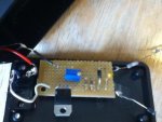
Step 3: Driver

Now, a few months back I put together the same set up for a LPC-815 red diode and it works just fine powered with two TrustFire 14500's.

But I'm putting together the same thing with same power supply and all, but I have replaced the 100 ohm potentionmeter with a 100 ohm trimmer. I set it up tonight and set up the test load to see what kind of current it was putting out. My driver for the red diode put out 273 mA which was exactly in the range of <300mA I needed. I've checked the charts for the PHR-805T and it operates in that same range so everything should work out correctly.

But now the problem. I hooked it up and it was really burning up the 1 ohm resistor in the test load. I mean, it got orange and melted the solder. Why is it doing that? The only thing I can think of is I didn't adjust the trimmer correctly. How do those little things work? Mine is a 3296 multi turn.

Any help on this? Why is it just frying the test load?


Joined
Jan 14, 2011
Messages
3,816
Points
63
Erm. That's not good. That's really really bad. Are you sure it's all hooked up right? Take a picture of your set up?
 
Joined
Aug 14, 2011
Messages
1,109
Points
0
273mA is going to fry that PHR diode. :undecided: Might want to bring it down a bit.
 

Things

0
Joined
May 1, 2007
Messages
7,517
Points
0
1. anything over 100mA is instant death for a PHR diode.
2. Trimmers are only rated for a few microwatts at best, your resistor needs to be capable of dissipating a bit more power than that. You may be able to get away with it for diodes under 100mA.

If the resistor is getting that hot, either it's insanely underrated, or you have wired it wrong.
 
Joined
Dec 22, 2010
Messages
227
Points
18
The voltage that the PHR draws is not equal to the LPC diode which will result in a different mA output than what you read out for a LPC diode over the 1ohm resistor. Did you set your testload to counter for the difference? And as Things said ^ anything above 100mA will fry your diode so its crucial that your testload is properly configured to measure the current correct.
 
Joined
Dec 11, 2011
Messages
4,364
Points
83
What is the power rating of the resistor you used? Probably 1/4watt, which would be why it got so hot.
 
Last edited:
Joined
Mar 11, 2012
Messages
215
Points
0
Everyone else beat me to it but I would just like to reiterate in case you missed it, 100mA is the max you should be pushing PHR-805T's. Also, if you are using the same setup of a test load as your red (3 or 4 silicon diodes to simulate Vf) you need to have six diodes in series to simulate a PHR. Also I would listen to Sigurthr and get a higher rated resistor.
 

Jwl456

0
Joined
Jan 24, 2012
Messages
16
Points
0
Thank you guys so much. I'll attach some pictures of my setup, and also of my successful red setup.

I did NOT change the test load to account for the PHR. Oops. I will definitely do that. But that doesn't change the amount of power the driver is putting out, right? I thought I had looked it up and the PHR ran in the same range as the LPC but I must have looked at the wrong thing. Should I change from the trimmer to a more robust linear wound 100 ohm pot like I used on the red one?
 

Jwl456

0
Joined
Jan 24, 2012
Messages
16
Points
0
Here's some pictures: 2 of the PHR setup (doesn't work) and 1 of the LPC (that works).
 

Attachments

  • PHR_1.jpg
    PHR_1.jpg
    29.2 KB · Views: 384
  • PHR_2.jpg
    PHR_2.jpg
    33.6 KB · Views: 258
  • LPC_1.jpg
    LPC_1.jpg
    34 KB · Views: 234

Jwl456

0
Joined
Jan 24, 2012
Messages
16
Points
0
The only thing I can think of that's wrong is that the trimmer isn't resisting anything. I think maybe I have it maxed out, I'm not really sure how to adjust these things properly.
 
Joined
Sep 12, 2007
Messages
9,399
Points
113
the 1 ohm resistor in the test load. I mean, it got orange and melted the solder. Why is it doing that?

The only way that's possible is: you've either measured the current improperly, or you used something higher than 1Ω.

273mW x 4.5V Vf = 1.22W of energy that resistor and trimmer has to support. What is the power rating of the resistor you used? Probably 1/4watt, which would be why it got so hot.

That's the power going to the diode, not the power dissipation for the current sense stuff. There's a constant 1.25V over it. For 5Ω, that should be ≈160mW per resistor. The trimmer will never dissipate more than 78mW. Math:

Ptrim = Itrim²Rtrim
Itrim = Itotal = 1.25/Rtotal
Rtotal = 5+Rtrim

Ptrim = [1.25/(5+Rtrim)]²Rtrim
Plot: maximum occurs at 5. 5 solves for 0.078.

They're rated for 1/2W (at least the first one I found on ebay was).

My suggestion is to check the voltage between adj. and out. Check the input voltage and check the output voltage. Double-check the values of resistors you are using.
 
Joined
Dec 11, 2011
Messages
4,364
Points
83
Yep, that post was full of stupid, sorry. Thanks for correcting it Cyparagon! I shouldn't answer questions in the middle of the night.


Top