Welcome to Laser Pointer Forums - discuss green laser pointers, blue laser pointers, and all types of lasers

LPF Donation via Stripe | LPF Donation - Other Methods

Links below open in new window

ArcticMyst Security by Avery

potentometers, resistors, and things (2nd design)

Joined
Aug 10, 2008
Messages
180
Points
0
I've been wondering about some random mods to the rkcstr driver I or others could do.... I've realized the little pot on it is hard to adjust, and got the idea of replacing it with resistors...
not just that, but maybe a few, and some wires and switches for good measure.

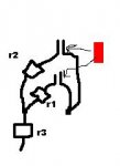
my idea is you set it at a desired power, measure resistance across it, possibly noting a few different resistance values, and then hunting down resistors to use/combine into those values. then using tiny wires and switches, you could have a selectable output without turning a tiny pot.
does this sound remotely possible or am I crazy?


Joined
Feb 23, 2008
Messages
2,832
Points
48
Re: potentometers, resistors, and things

sounds do-able but you should wait for some1 with a little more knowledge than me to confirm it.
 
Joined
Jul 24, 2007
Messages
2,749
Points
0
Re: potentometers, resistors, and things

I would say possible....as long as you are looking at building a labby type laser rather than a pointer.

You would need to run 2 wires ( I think 2 of the pots 3 legs are common) to another small board with a row of resistors and then maybe switch your values with a dip switch.

Regards rog8811
 

rkcstr

0
Joined
Dec 1, 2007
Messages
1,368
Points
0
Re: potentometers, resistors, and things

If you're looking for a specific value, I do have the fixed-value drivers as well.... most likely I can get a value close to anywhere in the range of my adjustable drivers that you want.

As for making a "selectable resistance switch" it would be possible, but you're not going to fit the parts on the board. I think Rog's suggestion of a DIP switch and a bank of resistors would be the easiest way since you could set it up to parallel resistances together to get the largest variance of values from the least amount of resistors.

And, you don't have to solder to the pads for the pot since they're pretty small, you can solder directly to anywhere connected to the two thru-hole points on the board to get a stronger connection (and you can remove the resistor on there as well). I would suggest you put some epoxy on that side of the board, covering the connections, so that you don't accidentally lift any pads due to movement of the wire.
 
Joined
Aug 10, 2008
Messages
180
Points
0
Re: potentometers, resistors, and things

I noticed my idea is similar to your driver with the many resistors on it...
I'll try to figure out what resistance the thing is set at for 300ma and maybe 70 since 70ma seems to be a good low power setting...
if i'm lucky i can fit a few of those little "jumper connectors" inside my dilda one on each side of the driver and move a jumper between the two to connect for a resistance value....

does radio shack carry tiny resistors or just normal itty bitty ones with the wires on each end?
I need a list of things to buy next time I go there haha

thanks in advance for everyone's help on my mad scientist ideas
 

rkcstr

0
Joined
Dec 1, 2007
Messages
1,368
Points
0
Re: potentometers, resistors, and things

www.vakits.com ... great place for some kits with a variety of values of various sizes.

Also, I have quite a few different values and could probably just mail some to you if you need.

As for the driver with "many resistors", my fixed-value drivers can fit up to 4 1206-sized SMD resistors.

You can figure out what resistance values you need with using the formula: Iout = 1.25V/Rset, or rearranged to solve for Rset = 1.25V/Iout. Just make sure you have Iout in A and not mA (ie 400mA is 0.4A).

One note for the resistors, make sure you have them with high enough power ratings for your output current... 1/2W is enough for up to ~400mA. Adding resistors in parallel or series is additive for power, so long as the values are equal, otherwise you can calculate individual power dissipations with some math.
 
Joined
Aug 10, 2008
Messages
180
Points
0
Re: potentometers, resistors, and things

looking at the room around the micro driver inside the dilda, my idea of a simple jumper pin thing just might work if I am careful...

I'm having a bit of trouble figuring out what is going on on the driver (looking at the pdf on stonetek's site on it) so I'll probably need some help with what to remove and where to place the wires when I get around to it... or maybe I'm just tired now haha

here is a doodle of my idea for the wiring I'd be adding...
I believe the part I need for the "switch" is called a pin header


[highlight]edit in[/highlight]
stopped by radio shack and went over the resistors they had, they had a large variety of ones that would be useful, but they were a quarter watt.... I picked up some 10ohm 22ohm and 33ohm half-watt resistors...
hopefully I can do something with those... or order some online
 

Attachments

  • switches3.JPG
    switches3.JPG
    5.9 KB · Views: 125
Joined
Aug 10, 2008
Messages
180
Points
0
Re: potentometers, resistors, and things

so i'm trying to figure out now what resistors I'd need to remove and what ones to leave on the driver so I can connect some external resistors...
it doesn't help that my driver doesn't look exactly like the blueprints that are on stonetek's site.

http://tinyurl.com/6h486o
pic in my photobucket ^

what points on the board should I measure from to find what resistance its set at? (for comparison to the mw rating I'm getting)

looking at the chart on one of the pdf's for a driver it seems like I need 4.1 ohm resistance for 300ma, does that sound right? with the resistors I have I can get about 4.3 ohms which could work. or if I wanted to get crazy I can do 3.6 ohms which is a little less than 350ma....

now I'm starting to doubt this can be done with the resistors I got at radio shack... I just might have to break down and buy some surface mount ones... or beg for them... haha

I still think its possible for me to be able to cram two jumpers and some resistors in there... its just gonna take some careful soldering of said resistors to wires and some ideas for what resistors to use.
 

rkcstr

0
Joined
Dec 1, 2007
Messages
1,368
Points
0
Re: potentometers, resistors, and things

http://rkcstr.googlepages.com/lpf

Look at the bottom for instructions for use and assembly (useful since you're modding).

You can measure the setting resistance across the two thru-hole points (see instructions).

If you need surface mount resistors, I have 8 different values. You can parallel multiple to get lower resistances.
 
Joined
Aug 10, 2008
Messages
180
Points
0
Re: potentometers, resistors, and things

oh cool theres some better info.... someone needs to bug greg to put that newer one up on his site haha.
it looks like my driver now is at 5.2ohms across the two holes, I'm thinking aiming for 5 would work. I have some 10's I could use but I'm starting to think surface mount ones would be a lot easier.... I'm going to tinker more after work for size and things
 
Joined
Aug 10, 2008
Messages
180
Points
0
Re: potentometers, resistors, and things

I'm not going to replace the driver because I put too much epoxy on it haha.  
it's fate is undecided, but its destiny will be a 405nm  after I break it  :p

I think I found a way to get the resistors crammed in there the way I want now...   heres a doodle of my idea...  
so all I need to remove is the pot and the two resistors adjacent to it right?

driver5.jpg


[highlight]edit in[/highlight]

now that i think about it, I could do an a/b/ab thing with it where one connector is high resistance, low power, the other is higher power, and both would combine for very high (still within limits tho)
I have tomorrow off I'll probably tinker with it then
 
Joined
Aug 10, 2008
Messages
180
Points
0
Re: potentometers, resistors, and things

the idea laid out

DSCN7688.jpg


I couldn't for the life of me get the wire through the "through hole" connections... I think the voltage regulator is covering both if thats possible haha
DSCN7693.jpg


the two 10's half way mounted.
DSCN7695.jpg


I twisted the other ends of the resistors together and tied to the other end of the wire (connecting where the switch would be) and tested with my multimeter, its only 250ma... I was hoping for more. at least the way I'm making it should make it easy to swap resistors if needed.

boredom got the best of me and I pieced it together. it could have gone a lot better but hey I'll save the doing better for next time.

high powered side, 250ma (175mw?)
DSCN7696.jpg


low powered side, which is way too low (about 50ma, I forgot)
DSCN7698.jpg


side view. I had to scrape away at the epoxy a bit to get the resistors to fit in the body. its a tight fit that needs more work... I swear they fit in my testing... haha.
DSCN7697.jpg


too tired now, will follow up late tomorrow maybe

final word, the dilda has room to play when you have a tiny driver board!
 
Joined
Aug 10, 2008
Messages
180
Points
0
Re: potentometers, resistors, and things

well I found a couple little things at the local radio shack that I thought could be useful...
I somehow assumed two parallel resistors made two quarter watt's good for a half... although I ended up using 3 in parallel.
happily the "kill" mode is at a healthy 290 ish ma power
and I fried the 22ohm for "point" mode =[ I can't be bothered to work on it anymore, too tired haha.


poor little switch, look so clean and new
DSCN7702.jpg


the little thing of desoldering braid I found at radioshack for 4 bucks works pretty good
DSCN7704.jpg


I've come to the conclusion the voltage regulator is a half of a mm too far to one side, so it somehow covers both thru holes on the board. oh well.

top side
DSCN7706.jpg


bottom side
DSCN7708.jpg


5000 hours in mspaint showing how it works... kinda
ms1.jpg


ms2.jpg


the green dot is the center pin of the switch, which went to the thru hole connector underneath where it is
everything blue connects to the other thru hole, that is on the edge of the board. the red lines are the a/b of the switch, going to the different groups of resistors.

sigh... what can I do next


Top