Welcome to Laser Pointer Forums - discuss green laser pointers, blue laser pointers, and all types of lasers

LPF Donation via Stripe | LPF Donation - Other Methods

Links below open in new window

ArcticMyst Security by Avery

PLD-40 Fiber coupled laser diode, for CNC cutting/engraving

Joined
Jan 29, 2014
Messages
12,031
Points
113
Well, mine did the same thing at what was probably a few amps too, I think we can't run the output anywhere near full output without having the fiber terminated into a connector, the reason why is the question.


Joined
Jul 10, 2015
Messages
9,907
Points
113
The end has to be polished clear like a diodes window, it also needs to be flat to slightly convex so the energy can get out and be focused by a lens.

Imagine the window on a multi watt blue laser diode was scratched up and opaque, it would burn up because the energy could not get out, well the fiber end is not polished clear and flat the energy can't get out and the end gets hot and burns up the cladding, you see in my pic how the glass core did not burn, it got hot and the cladding burned.

When we get our connectors/terminations we can score/pull and polish the fiber end flat and clear, then the energy will get to our lens, I have ordered one of those IR c-mount modules with the 808-1064 coated lens.

This >>> https://www.ebay.com/itm/Laser-Modu...997113?hash=item1eaf2d3fb9:g:qFEAAOSw3mpXGEHU


My end is not clear.

60020d1525482816-pld-40-fiber-coupled-laser-diode-cnc-cutting-engraving-burnout1c.jpg


The cladding burned off leaving the glass core with it's unclear end.

60022d1525482816-pld-40-fiber-coupled-laser-diode-cnc-cutting-engraving-burnout1a.jpg


This was before it burned, I thought it looked pretty good, apparently not good enough.

60019d1525479275-pld-40-fiber-coupled-laser-diode-cnc-cutting-engraving-polish2.jpg


---edit---

I just read that we are supposed to strip off that 125um buffer down to the 105um glass core, this may mean we need a connector/termination to fit 105um.

In case you don't see it somehow here's the other thread, Buontinh has one up and running. >>> https://laserpointerforums.com/f44/need-help-identifying-laser-module-102556.html
 
Last edited:
Joined
Jul 10, 2015
Messages
9,907
Points
113
Well we are learning so it's ok to make some OOPS smoke LOL

Member Buontinh just said that we need to remove the primary buffer before termination as well, we may also need a connector to fit the 105um glass core. >>> https://laserpointerforums.com/f44/f44/f44/f44/n...le-102556.html

Once we get these up and running I want to check into a fused biconic coupler to couple 3 or 7 pumps onto 1 fiber, that could be fun. :D

YIKES, these look a bit pricey, but where there's a will there's a hard way LOL >>> https://www.thorlabs.com/newgrouppage9.cfm?objectgroup_id=5606

----edit----

Actually those above are for splitting data fiber, here's some fiber couplers I think might work, I know they have a 6 to 1 for combining these very pumps we are working with.

https://www.thorlabs.com/search/thorsearch.cfm?search=fused+biconic+coupler
 
Last edited:
Joined
Jan 14, 2009
Messages
1,452
Points
83
I saw Dash apple had some other cool videos, seems like most of us brothers of the light also enjoy high voltage, LOL

Dash do you use any active cooling or just a heat sink on your 974 ?

Thanks , They do seem to go together - laser and high voltage : P .

Mine is just bolted to a heat sink , heat load is about 30W from the diode

I did intend to make a portable version and use a water cooled plate for the drivers and diode to make it as small as possible .
 
Last edited:
Joined
Mar 20, 2018
Messages
26
Points
0
This is just for future reference... This video shows us clearly that it needs to be stripped down to the bare core. If the fiber is scored with the bare core exposed, it breaks off easily.

 
Last edited:
Joined
Jul 10, 2015
Messages
9,907
Points
113
Yep, I stripped that tiny cladding off with basic wire strippers and years of stripping skill, turning the stripers at an angle to keep the fiber straight helps, and did a basic cleave, the end is not perfect but it works, however I will be aiming for a perfect polish when I get all my parts.

Here's a slow turn up to 5 amps test with no lens, I turned the current up slowly because if I smell the cladding I turn it off.....I wonder what's in that cladding, it's probably not healthy so I opened a window, no cladding was burned during this test, stripping then cleaving helps, but it's not perfect, however I did not polish it at all this time.
 
Last edited:
Joined
Mar 20, 2018
Messages
26
Points
0
Cool. It never gets old watching laser burn things up.

I too just tried using the cutting edges of a regular wire stripper to strip the coating off and to my suprise it was pretty easy. Unfortunately, something got stuck inside the ferrule of my terminator so I tried to clear it out using the fiber and it broke inside the ferrule. I searched high and low around the house, but just couldn't find anything small enough to clear out the hole. I should have bought two connectors. Now I have to wait for music wire before I can do anything https://www.amazon.com/FO4SALE-Piano-Wire/dp/B00FW867T8
I also made a polishing puck today as I have access to a lathe and didn't want to pay $20+ for something so simple.
 
Joined
Jan 29, 2014
Messages
12,031
Points
113
Looks like you put a fan on that to keep the smoke from depositing onto the end of the fiber, good idea, sure does burn well coming out of that glass waveguide.
 
Last edited:
Joined
Jul 10, 2015
Messages
9,907
Points
113
Here I slowly turned it up to 8 amps after breaking the fiber then cleaving it with wire strippers and stripping it again, actually cleaved it pretty well.

Even with the air moving it pumped in so much energy that the clothespin was fully lit, I only touched on 8a for a couple of seconds, I can see how running at 8-10a with a focusing lens these would make great home CNC cutters, how the output looks collimated through a lens at 15 feet I will find out as there are multiple emitters focused into the fiber, I would think they would be scrambled unlike the FAP bundle but we shall see.

We are supposed to use a scoring tool at the tip of the connector then pull the excess fiber away causing it to break at the score line, then polish with the coarse then 3 micron and finally 1/3 micron sheets, I am waiting for a scoring tool from China, it won't be here for weeks.

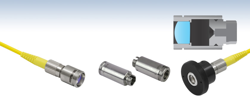
It may be possible to make a holder and set a lens in front, but keeping smoke and humidity away from the fiber end is likely a good idea, I plan to mount in THIS and use the supplied lens filling about 80% of the lens for as much reach as possible.

HERE is the scoring tool I ordered.


---edit---
Looks like you put a fan on that to keep the smoke from depositing onto the end of the fiber, good idea, sure does burn well coming out of that glass waveguide.

I can't take credit for that, it's just my window AC blowing across the room, well across the ceiling and down the big mirror on the wall in front of me and back across this table, it did seem to work out somewhat and looks like a fan blowing at me, but it's just how I have the air set up to circulate. :beer:
 
Last edited:
Joined
Mar 20, 2018
Messages
26
Points
0
Yeah, these fiber laser put out tons of heat even uncollimated. If you want the beam to stay collimated at longer distance, do you have to use like at least three lenses? First one to collimate the beam, second one to expand the beam, and then final one to collimate it again?

I made my cleaver pen out of a broken carbide end mill. I first grinded it to shape with a regular grinding wheel then sharpened it using a diamond wheel. Works like a charm.
 
Joined
Jul 10, 2015
Messages
9,907
Points
113
Yea, I figured it might need a beam expander after a primary, I am interested to see what the lens in the housing I'm waiting for will do as it looks to be about 15mm wide or there about.

So if I set my fiber end/termination back 25-50mm then I should be able to use most of that lens, so maybe the beam will exit about 12mm wide and be able to focus it reasonably tight at 15-20 meters.

I will find out once I get everything, also I do want to make a small TEC/fan cooling pad for the module as I noticed a little warmth after about 30 seconds at 8a the other day with the module stuck to a copper slab with silicon thermal gap pads, and I will want to run it for minutes at a time I'm sure.
 
Joined
Jan 29, 2014
Messages
12,031
Points
113
You could just let the beam output naturally expand to the size of the lens and then collimate, what I do is measure how wide the beam is at the distance I want the lens to be from the source, then find a lens which has that focal length for the diameter of the spot you want to collimate.
 
Joined
Jul 10, 2015
Messages
9,907
Points
113
I looked at the theoretical divergence but my viewer won't open the file, it's on a tab if you click on ( Complete Product Details ) then scroll down to that wavelength 980nm maybe you can view it. It's the 1st of the 3 for 980nm, F240FC-980 says 1.7mm beam dia. and there's a ( Raw Data ) tab. It look's like it's made to produce as decent as possible of a beam from your termination/connector. FC/PC

944_FC_PC-Collimator_6.jpg


Any beam will diverge or converge by some amount but looking at the description it's as if it's designed to make the best beam possible with your finished connector.

From the site:
These fiber collimation packages are pre-aligned to collimate light from an FC/PC-terminated fiber with diffraction-limited performance. Because these fiber collimators have no movable parts, they are compact and easy to integrate into an existing setup. Due to chromatic aberration, the effective focal length (EFL) of the aspheric lens is wavelength dependent. The design wavelength indicates the wavelength of ideal beam divergence (see the Divergence Info tab for more information).
 
Last edited:
Joined
Mar 20, 2018
Messages
26
Points
0
It shows divergence of .041 degree from 966nm to 994nm. Is that considered good or not?


Top