andy_con
0
- Joined
- May 24, 2007
- Messages
- 3,394
- Points
- 0
ok none of them photos are very good.
do one from the top so i can see everything
do one from the top so i can see everything


Follow along with the video below to see how to install our site as a web app on your home screen.
Note: This feature may not be available in some browsers.


andy_con said:ok right
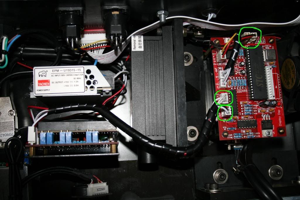
locate the PSU for each item.
there should be a psu for the galvos, the psu will connect to the galvo amp.
there should be a psu for the green laser and psu for the red lasers.
coming from each laser psu there should be a black and red wire going into the dmx, these will be your TTL wires.
from the galvo amp there should be three wires XYG going into the dmx.
these are all the wires you need to hok up to a DAC
")


")