Welcome to Laser Pointer Forums - discuss green laser pointers, blue laser pointers, and all types of lasers

LPF Donation via Stripe | LPF Donation - Other Methods

Links below open in new window

ArcticMyst Security by Avery

PHR-803T  DDL Driver Circuit Question

Joined
Mar 15, 2009
Messages
74
Points
8
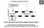
Hey everyone! I ordered a PHR803T Sled for 14 $ and I am waiting for it to arrive at my house! I built a DDL circuit. If you go to the FAQ, go to the link that brings you to the driver circuit, the one in the green, with a 25-ohm pot. I am afraid that it might kill my diode. I hope that I can get all the help I can get.  :)

EDIT:

Its working! I am running at around 80 - 100mW.

Here is a link to my new laser topic!


Joined
Oct 26, 2007
Messages
5,438
Points
83
Just measure the current output on your driver and make sure it's not too high before connecting the laser diode to it. Make sure to short the leads before soldering the diode on to remove any charge.
 
Joined
Mar 15, 2009
Messages
74
Points
8
How exactly is this done? I heard to put like 4 1N4001 Diodes on it or something like that... I need some help because I am new to this laser business.

28m2sns.png
 
Joined
Mar 15, 2009
Messages
74
Points
8
Okay, Well sorry about the blurriness. I can blame my camera for that one.

Here is the schematic I am using for my diode. The power supply is actually 9v not 6v.

1zx6t8j.jpg


and a noob-tacular one
2w3zus8.png
 
Joined
Oct 26, 2007
Messages
5,438
Points
83
Put a dummy load where the laser diode would go and measure the current on it.

As for your camera, try stepping back, taking a focused shot, and then crop it down to size.
 
Joined
Jul 4, 2008
Messages
347
Points
18
6 1N4001 diodes and a 1 ohm resistor for a Blu-ray, 4 1N4001 diodes and a 1 ohm resistor for a Red
 
Joined
Jul 24, 2007
Messages
2,749
Points
0
Like this.....
 

Attachments

  • test_load01_010.jpg
    test_load01_010.jpg
    41.2 KB · Views: 1,692
Joined
Mar 15, 2009
Messages
74
Points
8
So, I am new to this, I attach the multimeter to the black and red spots and measure in what? Volts, resistance (ohms,) etc.

Thanks In advance!
 

Warske

0
Joined
Mar 10, 2009
Messages
145
Points
0
Clickey said:
So, I am new to this, I attach the multimeter to the black and red spots and measure in what? Volts, resistance (ohms,) etc.
Measure volts across the 1 ohm resistor.

Then use ohms law to figure out how many amps are going through the resistor, and set your pot for the number of amps you want to drive the laser diode at.  (Hint, for a 1 ohm resistor, Amps = Volts).
 
Joined
Jul 24, 2007
Messages
2,749
Points
0
So, I am new to this, I attach the multimeter to the black and red spots and measure in what? Volts, resistance (ohms,) etc.  

I know this has been answered above but could I just point out that the drawing I posted, just above your post, the wording says "connect to driver circuit where laser diode will go" (the picture shows the positive and negative connections for blu ray and red laser diodes). It also shows a meter connected to the circuit, in the correct place, and underneath that is written how the meter is set and what the reading means.
So where it says "measure mv" = meter is set to measure mv.

Again as stated above, using a 1ohm resistor in the test load there is no calculation required, the reading on the meter in mv is equal to the output of the driver in ma.

Regards rog8811


Top