Welcome to Laser Pointer Forums - discuss green laser pointers, blue laser pointers, and all types of lasers

LPF Donation via Stripe | LPF Donation - Other Methods

Links below open in new window

ArcticMyst Security by Avery

OPT Lasers Cylindric lenses - NUBM44 beam correction tests

Joined
Jul 10, 2015
Messages
9,888
Points
113
Yes you can use a wave plate to match beam profiles going into your cube, I don't think that energy density is any problem, think about the area your beam will cover, you should be fine.
 
Last edited:


Joined
May 17, 2016
Messages
22
Points
0
I don't think so. All of the schematics I've seen for Galilean beam expanders mostly use two lenses. One a negative pcv, the other a positive pcx. Occasionally you'll see a beam expander with two lenses cemented together or spaced very close together. What's your application for the beam expander? One thing to keep in mind is to make sure the pcx lens has a diameter large enough so it does not truncate the sides of the beam as the beam passes through it.

What's nice about Edmund Optics is they carry a large number of in stock AR and non AR coated lenses.

The Galilean style expander is what I'm planning with Edmund parts listed somewhere above. By collimator, I mean something to replace the G2, three lens, etc.

Correct me if I'm being naive, but with regard to high power laser diodes, the perfect optics setup for low divergence is an initial collimator, then a 1-axis corrector, then a 2-axis expander. With the Edmund parts listed above, I'm going to assemble the cylindrical 1-axis corrector and the expander. With the aspherical lenses, I was proposing an alternative to the typical collimators. How could we assemble one from Edmund?
 
Joined
Jul 10, 2015
Messages
9,888
Points
113
You have a highly divergent beam coming out of the diodes window, a window that has to be kept exceptionally clean and is dam hard to clean, especially if anything gets burnt into its AR coating.

The beam diverges so rapidly that it gets clipped by the 1/4 inch of lens threads, without a M9 x 0.5 housed lens to get up close to that window and protect it you have a floodlight, you would have to mount your diode flat and open faced, then seal your lens set up and it, that's silly, just screw in a G2, they are very efficient.

Then work from there by shaping the fast axis only and then use a standard round expander.
 
Last edited:
Joined
Jun 3, 2007
Messages
2,560
Points
113
The Galilean style expander is what I'm planning with Edmund parts listed somewhere above. By collimator, I mean something to replace the G2, three lens, etc.

Correct me if I'm being naive, but with regard to high power laser diodes, the perfect optics setup for low divergence is an initial collimator, then a 1-axis corrector, then a 2-axis expander. With the Edmund parts listed above, I'm going to assemble the cylindrical 1-axis corrector and the expander. With the aspherical lenses, I was proposing an alternative to the typical collimators. How could we assemble one from Edmund?

I would approach the design by first correcting the beam profile then pass the beam through a collimator. Aspheric lenses have short focal lengths, they won't give low divergence. By low I mean less than 1mrad. You can calculate the power of a Galilean beam expander by dividing then positive focal length by the negative focal length. Same goes for Keplerian expanders. But experiment with different type lenses your approach might work too. Edmund has a site called Anchor Optics.com. Take a look a the site Light Machinery.com optical apps especially the Gaussian beam expander one.
 
Last edited:
Joined
May 17, 2016
Messages
22
Points
0
you would have to mount your diode flat and open faced, then seal your lens set up and it, that's silly, just screw in a G2, they are very efficient.

Then work from there by shaping the fast axis only and then use a standard round expander.

It is the mark of an educated mind, according to Aristotle, to be able to entertain an idea without accepting it. Machining an aluminum or copper block with a hole that holds a diode on one end and a small lens on the other is very simple. As such, if substantial gains in efficiency or divergence could be had by using using something other than a G2, G7, etc., it would be prudent to at least discuss doing so.

As steve pointed out, the VIS 0 coating from Edmund has an amazing 0.2% reflectance for the visible spectrum and is very affordable. My current goal is to use these lenses for the fast axis correction lenses and also for the 2-axis "round expander" using the parts I mentioned before. However, after that, I would be interested in seeing if improvements could be made over the standard collimators. But, I have no idea what type of lens is in a G2, G7 or any kind of single lens laser pointer collimator. As I said earlier, I'm assuming it would be what is called an aspheric lens.

I read on Newport (link) that any lens set expansion ratio is determined by the ratio of the lenses' focal length. For example, a PCV lens with -25mm FL combined with a PCX lens with a 100mm FL differs by a factor of four, therefore it is a 4x expander. I also read that the spacing between these lenses is the sum of their back focal lengths. What I still don't know is should one attempt to design an expander that short focal lengths and short spacing, or longer focal lengths and longer spacing. Are there any advantages to one or the other?
 
Joined
May 17, 2016
Messages
22
Points
0
I would approach the design by first correcting the beam profile then pass the beam through a collimator. Aspheric lenses have short focal lengths, they won't give low divergence. By low I mean less than 1mrad. You can calculate the power of a Galilean beam expander by dividing then positive focal length by the negative focal length. Same goes for Keplerian expanders. But experiment with different type lenses your approach might work too. Edmund has a site called Anchor Optics.com. Take a look a the site Light Machinery.com optical apps especially the Gaussian beam expander one.

To achieve correction of the beam profile prior to collimation, I assume that would involve placing a cylindrical PCV almost directly against the diode, correct?

Another benefit of using this approach would that there are now only two total steps (correction, collimation/expansion) rather than three (collimation, correction, expansion). Thoughts?

Edit:
I found this drawing of a G2 lens. I assumed that since the front and back of the lens were not the same, that it would be called aspherical, but I see now that means something different. How does one go about choosing a lens based on the angle of the beam coming out of the diode to collimate it?

RDoYLtG.png
 
Last edited:
Joined
Jul 10, 2015
Messages
9,888
Points
113
This is part of what I meant to convey, the DTR G2 I believe is made by Coherent and is very efficient, I don't see a significant amount of gain in doing it differently.

Now if we could get a tiny fused silica or quartz fast axis corrective optic right at the emitter then a tiny aspheric lens or a tiny expander pair then a useable tight beam could be had in a compact package.

The NUBM06 with it's better divergence and Gball lens construction would be a good candidate, I would love to see you guys do something like that with this diode.

The larger square is an anti static device, the long tiny part to the right is the emitter, it all comes out of that tiny window, if you could correct it there then use a tiny expander to make a needle thin fixed focus beam that would be epic.
Do you think it's possible? Maybe you could construct a tiny mount that would attach to the front of the waveguide and hold the optical train right there, this would make a compact unit much easier, with proper heat dissipation and a suitable battery for the boost drive the super thin 7 watt beam could be the size of a roll of half dollars, the 1 26650 IMR would be the biggest part.

NUBM06 9mm wide diode with Gball lens can removed.

51640d1464139643-opt-lasers-cylindric-lenses-nubm44-beam-correction-tests-sany0006.jpg


Capture_04252016_141915_zpsiytfqlai.png


Capture_04252016_141634_zpsnlrckfgc.png
 

Attachments

  • SANY0006.JPG
    SANY0006.JPG
    167.6 KB · Views: 590
Last edited:
Joined
May 17, 2016
Messages
22
Points
0
The larger square is an anti static device, the long tiny part to the right is the emitter, it all comes out of that tiny window, if you could correct it there then use a tiny expander to make a needle thin fixed focus beam that would be epic.
Do you think it's possible? Maybe you could construct a tiny mount that would attach to the front of the waveguide and hold the optical train right there, this would make a compact unit much easier, with proper heat dissipation and a suitable battery for the boost drive the super thin 7 watt beam could be the size of a roll of half dollars, the 1 26650 IMR would be the biggest part.

Firstly, brilliant pics. Amazing how much light comes out of such a small area.

The only problem with needle thin is that it will have high divergence. Maybe if you are after a burner that is OK, but I'm after low divergence and a beam that is visible for as far as possible. I want to scare Martian children.

I do align with you on compactness, though. Help me calculate what lens needs to be placed against the diode and I will follow through. Edmund sells lenses as small as 1mm diameter with 0.6mm FL.

Edit:
I think I found some direction:

iaq9YdO.png


Edit 2:
I guess I was right after all. Aspheric lenses are highly suited for initial laser diode collimation.
Thors Labs Link
 
Last edited:
Joined
Jun 3, 2007
Messages
2,560
Points
113
To achieve correction of the beam profile prior to collimation, I assume that would involve placing a cylindrical PCV almost directly against the diode, correct?
I don't know. I don't see why spacing would have to be so close


I found this drawing of a G2 lens. I assumed that since the front and back of the lens were not the same, that it would be called aspherical, but I see now that means something different. How does one go about choosing a lens based on the angle of the beam coming out of the diode to collimate it?

RDoYLtG.png
Edmund calls this type of lens a "best form" lens as I recall. It's not the lens you'd want to use. A long focal length plano-convex lens is what should be used. Double-convex can be used to but are difficult to mount evenly because of their curvature.
 
Last edited:
Joined
Jun 3, 2007
Messages
2,560
Points
113
Firstly, brilliant pics. Amazing how much light comes out of such a small area.

The only problem with needle thin is that it will have high divergence. Maybe if you are after a burner that is OK, but I'm after low divergence and a beam that is visible for as far as possible. I want to scare Martian children.

I do align with you on compactness, though. Help me calculate what lens needs to be placed against the diode and I will follow through. Edmund sells lenses as small as 1mm diameter with 0.6mm FL.

Edit:
I think I found some direction:

iaq9YdO.png


Edit 2:
I guess I was right after all. Aspheric lenses are highly suited for initial laser diode collimation.
Thors Labs Link
Did you check out the app at Light Machinery for calculating beam divergence? The smallest negative focal length lens I would use would be a -6 by 6mm diameter because it's difficult to center lenses smaller than that.
 
Joined
Jun 3, 2007
Messages
2,560
Points
113
As steve pointed out, the VIS 0 coating from Edmund has an amazing 0.2% reflectance for the visible spectrum and is very affordable. My current goal is to use these lenses for the fast axis correction lenses and also for the 2-axis "round expander" using the parts I mentioned before. However, after that, I would be interested in seeing if improvements could be made over the standard collimators. But, I have no idea what type of lens is in a G2, G7 or any kind of single lens laser pointer collimator. As I said earlier, I'm assuming it would be what is called an aspheric lens.
Aspheric means the curvature is not uniform over the lens surface. It doesn't tell you what type of lens it actually is.

I read on Newport (link) that any lens set expansion ratio is determined by the ratio of the lenses' focal length. For example, a PCV lens with -25mm FL combined with a PCX lens with a 100mm FL differs by a factor of four, therefore it is a 4x expander. I also read that the spacing between these lenses is the sum of their back focal lengths. What I still don't know is should one attempt to design an expander that short focal lengths and short spacing, or longer focal lengths and longer spacing. Are there any advantages to one or the other?
I'll get back to this part later.
Ok. To answer this question I would use a short focal length -6 PCV lens and a long positive focal length PCX lens. Playing around with that Light Machinery app and using -6 pcv lens and a 100 mm focal length pcx lens with those two I could get a long Rayleigh Range. Your goal is a long Rayleigh Range also known as Rayleigh length. This term means the beam as it exits the beam expander will only expand 1.4 times its diameter, once passed that range the beam expands like a flashlight beam. Capice?


P.S. What you are doing I find far more interesting than someones balloon popping vid or I wanna laser that burns
 
Last edited:
Joined
Jul 10, 2015
Messages
9,888
Points
113
The size of the emitter and the initial divergence are the limiting factors, and of course what lenses are available.

No beam is truly stable, it always is converging or diverging by some amount, but finding a beam diameter based on the 3 parameters above you can create a beam that appears to hold steady into the distance, or even converge into the distance, but the far field spot will be larger than it looks as the spot size is a multiple of the focal length and the emitter size / divergence and can not ever truly hold steady.

That is a 3mm wide beam is impossible to remain 3mm wide over 10 kilometers But you can make it appear that way to the eye.

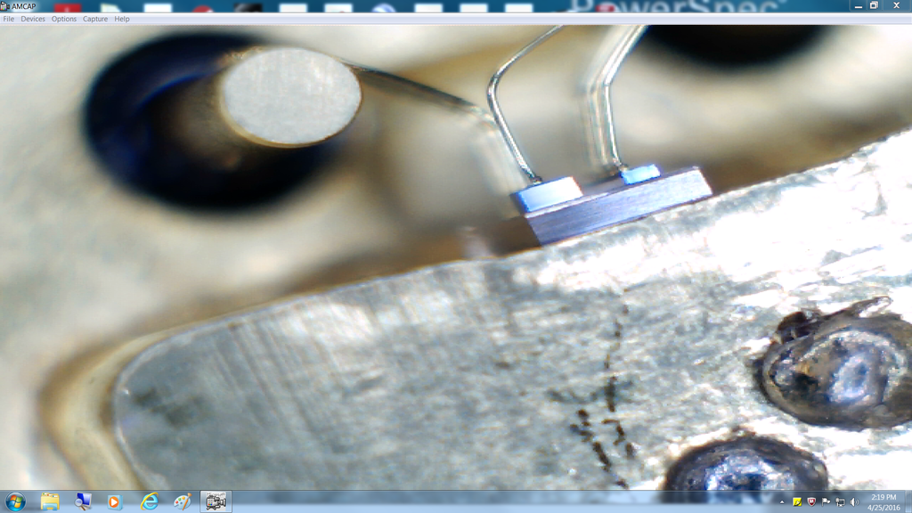
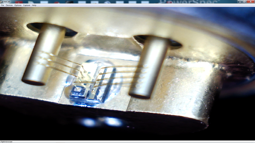
To get the most power at distance means starting wide and finishing small, a cone shaped beam, that and it's MULTI MODE, a single mode emitter would be easier but multi mode means the center wavelength has adjacent wavelengths at a lower power lever and that makes for the shadow wings around the beam.

th


But I like what you are trying to do, but the radical and uneven divergence of a rectangle shaped emitter that diverges opposite of it's shape creates a real challenge to creating the appearance of the perfect beam, being multi mode adds to the problem.

I would like to see a better compromise and starting closer to the emitter reduces the number of optics needed to maintain a smaller diameter beam, but with 0.2 percent loss many optics could be used, my problem is how one lens effects the next, the more lenses the more complicated it gets. Alignment of multiple optics is another factor and 0.2% reflectance is great, but is that the total parasitic loss or is there more loss through the lens as well......using as few lenses as possible is usually good.

Starting close helps because as you stated above " No matter what lens is used, the beam radius and beam divergence have a reciprocal relation, so to improve collimation by a factor of 2 you need to increase the beam diameter by a factor of 2 ".
 
Last edited:
Joined
Jun 3, 2007
Messages
2,560
Points
113
To achieve correction of the beam profile prior to collimation, I assume that would involve placing a cylindrical PCV almost directly against the diode, correct?

Another benefit of using this approach would that there are now only two total steps (correction, collimation/expansion) rather than three (collimation, correction, expansion). Thoughts?

Edit:
I found this drawing of a G2 lens. I assumed that since the front and back of the lens were not the same, that it would be called aspherical, but I see now that means something different. How does one go about choosing a lens based on the angle of the beam coming out of the diode to collimate it?

RDoYLtG.png

I think this lens type performs like two lens cemented together.
The only thing to be concerned about is making sure the diameter of the lens is greater than the beam diameter, if not the beam's side will be truncated.
 
Last edited:
Joined
Jul 10, 2015
Messages
9,888
Points
113
Yes and I am running into that right now with DTR's G2 a 6x pair and my 3x expander I can't get long distance focus, the diode is a nubm44.

I am getting some impressive results with a NUBM44 and Podo's G2 a 6x pair from LSP and Podo's 3X expander, There is nothing in my 75 feet of backyard that I can't burn, however replicating this with DTR's G2 and yes the beam fits into the expander and I align it, is not obtaining the reach.

In my nubm06 burning videos DTR's G2 will run convergence then divergence while cutting wood sticks at 6 inches, but Podo's G2 only gets tight up close and to get an infinity focus with the DTR G2 and 6X My beam runs converge/diverge with the sweet spot at 6-8 feet.

Until I understand this I recommend buying a SANWU G2 to have on hand.

The DTR G2 is a good lens but I may need to change my setup or get a wider expander, why Podo's G2 works so well with the expander after shaping I don't know.

Maybe I am doing something wrong, but one lens effects the next and something about Podo's G2 it making it work at 5 feet to 75 feet I can get it very flame throwing tight.

Now without the expander and just the 6X pair I get about a 3/4 inch line at 32 feet as seen in my shirt burning test, and I ignite paper at 0 -20 feet just fine, but it won't fly with the expander past 6 feet, not to a tight focus and at 14 feet its a 1/4 inch round spot so it's clipping or as you say truncating, maybe I need a relay lens expander for this to work, I am going to try adjusting everything else but this is strange.
 
Last edited:
Joined
Jun 3, 2007
Messages
2,560
Points
113
Yes and I am running into that right now with DTR's G2 a 6x pair and my 3x expander I can't get long distance focus, the diode is a nubm44.

I am getting some impressive results with a NUBM44 and Podo's G2 a 6x pair from LSP and Podo's 3X expander, There is nothing in my 75 feet of backyard that I can't burn, however replicating this with DTR's G2 and yes the beam fits into the expander and I align it, is not obtaining the reach.

In my nubm06 burning videos DTR's G2 will run convergence then divergence while cutting wood sticks at 6 inches, but Podo's G2 only gets tight up close and to get an infinity focus with the DTR G2 and 6X My beam runs converge/diverge with the sweet spot at 6-8 feet.

Until I understand this I recommend buying a SANWU G2 to have on hand.

The DTR G2 may well be truncating because I can get tight with the 3X after the 6X pair until about 6 feet but after that it will not get sharp, and yes I have it centered and aligned.

Maybe I am doing something wrong, but one lens effects the next and something about that concave input of Podo's G2 it making it work at 5 feet to 75 feet I can get it very flame throwing tight.

Now without the expander and just the 6X pair I get about a 3/4 inch line at 32 feet as seen in my shirt burning test, and I ignite paper at 0 -20 feet just fine, but it won't fly with the expander past 6 feet, not to a tight focus and at 14 feet its a 1/4 inch round spot so it's clipping or as you say truncating, maybe I need a relay lens expander for this to work, I am going to try adjusting everything else but this is strange, hopefully Podo doesn't run out of lenses as I have more to build.

What's your objective again? Outline it. Be concise and don't use abbreviations. Such as LSP, I have know clue what that means.
 
Last edited:
Joined
Jul 10, 2015
Messages
9,888
Points
113
The expander objective is 25.4mm "1 inch" wide and my beam is 6.5mm wide as corrected by a 6x cyl pair, the diode is a nubm44, the expander is a 3.3x, I am all for finding new ways but I am still learning lenses.
LSP is laser show parts.
If you wanted to talk engines I can explain rod to stroke ratio, volumetric efficiency, why a medium duration high lift cam is better than a long duration for a daily driver, how intake, exhaust, and head flow matters and why less can be more, how electronic control eliminates the old pre ignition issues with forced induction and on and on, but lenses I need to learn and I want to, and I will, and I am all for finding a new better way.

I think I may need a wider expander for the 44 to use the standard G2 but with Podo's it works, maybe I need to adjust a bit as to my cyl pair position to the lens.
Also I just got my M12x.5 tap and it's a 1.5 pitch they sent, dam it, hurry up and wait, I want to get another nubm06 and use this set up, I think it will do very well with the 3.3x expander.

Podo's G2 is not concave at the back, that was an optical illusion of the front curvature, seen through the back.
 

Attachments

  • podoG2notCONCAVE2.bmp
    749.2 KB · Views: 176
Last edited:


Top