Welcome to Laser Pointer Forums - discuss green laser pointers, blue laser pointers, and all types of lasers

Buy Site Supporter Role (remove some ads) | LPF Donations

Links below open in new window

FrozenGate by Avery

OPT Lasers Cylindric lenses - NUBM44 beam correction tests

The expander objective is 25.4mm "1 inch" wide and my beam is 6.5mm wide as corrected by a 6x cyl pair, the diode is a nubm44, the expander is a 3.3x, I am all for finding new ways but I am still learning lenses.

Ok, the beam after correction is 6.5mm wide. you have an objective which is 25.5 mm in diameter. Is this objective a positive lens or a negative lens? If positive what is the focal length? If positive what type of lens is it? What is the focal length of the other objective


LSP is laser show parts.
I
I think I may need a wider expander for the 44 to use the standard G2 but with Podo's it works, maybe I need to adjust a bit as to my cyl pair position to the lens.

Forget about the G2 lens, the focal length is much too short for your application as is its diameter. Your beam is already 6.5mm in diameter. You need lenses with a greater diameter than the beam in order not to truncate the beam.
 
Last edited:


So this is why Podo's G2 works, because it has a longer FL and is wider, what's funny is I still get the same sort of correction through my 6x cyl pair, but as I showed in the pic with podo's G2 I have to set the cyl concave very close, my zoomed in bar is insanely tight, lots of splash from a dirty window, but the zoomed down bar is really tight.

How upstream lenses effect downstream lens interaction when the beam looks the same screws with me, but I have seen it before.

Thanks for the explanation. :)

p.s. Wouldn't a wider expander also work with the short FL G2? I can see how it fits in the lens output and it is tight to try and center it and my long range is not as tight, that's because of the PodoG2's longer Fl prior to correction? See that screws with me, but I think I get it. It's a multiple of the FL at a trade off for beam width.

I think the physically larger OPT cyl pairs will be needed with the G7.

I have always been a fan of longer FL wider lenses but the problem is the wings with these MM diodes.

That's why I want to correct the highly divergent axis first, then use a wider - and + expander set.
 
Last edited:
I don't know. I don't see why spacing would have to be so close

Edmund calls this type of lens a "best form" lens as I recall. It's not the lens you'd want to use. A long focal length plano-convex lens is what should be used. Double-convex can be used to but are difficult to mount evenly because of their curvature.
My initial impulse to place it so close was simply because of the extreme divergence of the raw output from the diode. The necessary width of the lens quickly becomes very large the further it is from the diode. According to the NDG7475 datasheet (link) the "typical" divergence is 11 degrees on one axis by 46 degrees on the other axis. These numbers range from the minimum of 5 and 35 to the maximum of 25 and 55, respectively.

Did you check out the app at Light Machinery for calculating beam divergence? The smallest negative focal length lens I would use would be a -6 by 6mm diameter because it's difficult to center lenses smaller than that.
Aspheric means the curvature is not uniform over the lens surface. It doesn't tell you what type of lens it actually is.

I'll get back to this part later.
Ok. To answer this question I would use a short focal length -6 PCV lens and a long positive focal length PCX lens. Playing around with that Light Machinery app and using -6 pcv lens and a 100 mm focal length pcx lens with those two I could get a long Rayleigh Range. Your goal is a long Rayleigh Range also known as Rayleigh length. This term means the beam as it exits the beam expander will only expand 1.4 times its diameter, once passed that range the beam expands like a flashlight beam. Capice?

P.S. What you are doing I find far more interesting than someones balloon popping vid or I wanna laser that burns
Yes, I am using the app now. Click the Send button, then click To Colleague, then copy and paste the URL here. This should allow me to see the model you have created.

I'm attempting to create a model that simulates an NDG7475 with the lowest divergence physically possible while maintaining a sufficiently small beam diameter to provide a high enough power density for a bright beam and spot. These two objectives are both necessary, otherwise to get the lowest possible divergence, one would simply create the largest beam diameter possible, the power density of which would be too low to create a highly visible beam and spot at great distances.

I am using 2mm for the Beam Waist Diameter and 800 mRad for Full Angle Beam Divergence. Using an online calculator (link), 46 degrees (the raw major axis divergence of my diode) equals 802 mRad, but 800 will make the math simpler. I will need to spend some more time experimenting with my train of lenses before I post a model that has any value.
 
So this is why Podo's G2 works, because it has a longer FL and is wider, what's funny is I still get the same sort of correction through my 6x cyl pair, but as I showed in the pic with podo's G2 I have to set the cyl concave very close, my zoomed in bar is insanely tight, lots of splash from a dirty window, but the zoomed down bar is really tight.

How upstream lenses effect downstream lens interaction when the beam looks the same screws with me, but I have seen it before.

Thanks for the explanation. :)

p.s. Wouldn't a wider expander also work with the short FL G2? I can see how it fits in the lens output and it is tight to try and center it and my long range is not as tight, that's because of the PodoG2's longer Fl prior to correction? See that screws with me, but I think I get it. It's a multiple of the FL at a trade off for beam width.

I think the physically larger OPT cyl pairs will be needed with the G7.

I have always been a fan of longer FL wider lenses but the problem is the wings with these MM diodes.

That's why I want to correct the highly divergent axis first, then use a wider - and + expander set.
I think I misunderstood what type of a lens a G2 is, what is it?
Does MM stand for multi-mode?
 
My initial impulse to place it so close was simply because of the extreme divergence of the raw output from the diode. The necessary width of the lens quickly becomes very large the further it is from the diode. According to the NDG7475 datasheet (link) the "typical" divergence is 11 degrees on one axis by 46 degrees on the other axis. These numbers range from the minimum of 5 and 35 to the maximum of 25 and 55, respectively.
Placing it close makes sense if the optic isn't large enough to accommodate the full width of the beam.


Yes, I am using the app now. Click the Send button, then click To Colleague, then copy and paste the URL here. This should allow me to see the model you have created.

I'm attempting to create a model that simulates an NDG7475 with the lowest divergence physically possible while maintaining a sufficiently small beam diameter to provide a high enough power density for a bright beam and spot. These two objectives are both necessary, otherwise to get the lowest possible divergence, one would simply create the largest beam diameter possible, the power density of which would be too low to create a highly visible beam and spot at great distances.

I am using 2mm for the Beam Waist Diameter and 800 mRad for Full Angle Beam Divergence. Using an online calculator (link), 46 degrees (the raw major axis divergence of my diode) equals 802 mRad, but 800 will make the math simpler. I will need to spend some more time experimenting with my train of lenses before I post a model that has any value.[/QUOTE]
A divergence of 800mrad can not be true. The maximum is 360 degrees. I changed one parameter in each, the diode axis.
https://lightmachinery.com/optical-...-beam-propagation/?key=u3kHdehfK0GB9p7C_RnJ4A

https://lightmachinery.com/optical-...-beam-propagation/?key=RdNYR9j1mUiDv1OpOUGyTg
 
Last edited:
Hi RC,

By Podo G2 is this what you mean?

https://www.sanwulasers.com/product/lenses

Yes.

The DTR G2 and the SANWU G2 will both focus to a cutting thin line that cuts so thin it will not impart energy into the adjacent material to the cut, so you can cut without igniting.

The DTR G2 can be focused to do this over a range of 0 to several inches but podo's G2 only gets tight up close, so it is a different focus and it makes a much tighter spot through the 3X expander after cyl correction on the nubm44 diode.

51666d1464388693-opt-lasers-cylindric-lenses-nubm44-beam-correction-tests-sany0408.jpg


The diode in the video is a nubm06 with sawnu G2.

Here is a DTR G2, you see how it's tight focus can be set further out.
This may be good for CNC but not for my use with 6x pairs and podo's 3X, podo's G2 makes the difference there, I have been adjusting and can not match the SAWNU G2 performance with 6X and 3X expander, maybe if I had a larger expander.

This is nubm06 with DTR G2


NOTE with the 6X CYL pair I set the G2 to an infinity focus, I have also tried 5 meters, but only the SANWU will work right with the 3x expander after correction.

-------------------------------------------------------------------------------------------------------

I just put a SANWU G7 on a NUBM44 build, focused it to 20 feet and held SANWU's 3x expander in place with a 1/4 inch spacer, I am still waiting for the right tap, but running through the focus this is a good set up.
SANWU's G2 plus my 6x pair and his 3X expander is amazing.
But just the G7 and 3x is a huge improvement over the old 3 element or G2 option, a huge improvement.
I can see where the SANWU 5W with G7 and 3X was thought up, the lenses are worked out well.
 

Attachments

  • SANY0408.JPG
    SANY0408.JPG
    168.9 KB · Views: 596
Last edited:
Last edited:
By Podo 3x BE you mean sanwu one from the same shop, right?

What size is the beam entrance hole?

I also bought the 10x from Jetlasers like you did, but the opening is so small (5mm) that it will never let any KEdged MM beams in, set apart cylindrically expanded.
I tried to unscrew the small lens and maybe replace it by a bigger one but the thread is blocked, I only almost broke my seeger pliers.
 
8mm rear input opening and 25.4 front output and designed for use with our MM diodes.

Install a G7 lens and focus to infinity, or 20 feet is a nice medium and the expander is M12x0.5 threads so you can tap your 12mm module hole and screw it in. SANWU's lasers come already threaded for the expander.

It has a nice adjustment range and the G7 and 3x I just had on a nubm44 was lighting paper on fire at 15 feet, an absolute huge improvement over a 3 element or G2, the G7+3X makes a laser out of a fan shaped floodlight.

With a SANWU G2 and my 6x cyl correction then the 3X expander the results are amazing, I can burn at 75 feet.

The biggest lens is the 1 inch objective of the 3x, it is possible to tame these 5w diodes with pocket sized lenses, I'm glad Podo knows what he's doing.

I may give in and get a Spiker with the 7A75, G7 and a 3X, it just looks so good and the lenses work.

But in answer to your question the rear opening is 8mm in the clear, works great with all our M9x0.5 lenses and MM diodes.
 
Last edited:
Your models have a low initial beam divergence. Shouldn't we be using the divergence directly from the diode?

Edit:
There are 17.45 milliradians in one degree. The Light Machinery app allows up to 1000 milliradians, or one radian, or 57.29 degrees.

Let me back up a bit. Something isn't making sense and some information is missing. If memory serves the fast axis angle is 35 degrees, the slow 5 degrees of this diode. The fast axis equals about 612 milli-radians. That means the beam 1 meter from the bare diode has a diameter of 612 mm or 24.0945 inches. See how problematic that would be engineering an optical system if the beam is expanding at such a fast rate. At one meter what is the diameter of the spot made by the bare diode?
Slow
https://lightmachinery.com/optical-...-beam-propagation/?key=4f3qgv08lUu1__h11Zeiwg
fast
https://lightmachinery.com/optical-...-beam-propagation/?key=zpsInlSLxU-Gj-DT29XIPQ
Let's assume I've done things right. Look at the Rayleigh Range (RR) number. That number in feet comes to over 8000. That means your spot size out to that distance would be 2.2 inches in diameter and beyond that distance it would expand at 0.016mrad


I did one more. I place the beam expander 1mm from the diode left all other numbers the same. Note the difference.
https://lightmachinery.com/optical-...-beam-propagation/?key=YRMpkdUqPEuJUNXYNh-zeA
 
Last edited:
The size of the emitter and the initial divergence are the limiting factors, and of course what lenses are available.

The first part of your statement is profoundly accurate. As noted in Application 2 in this link, which I referenced in an image before, the divergence of the beam can be calculated by dividing the emitter size by the focal length of the lens.

The second part of your statement is not accurate. Initial divergence can be corrected.

When using the Light Machinery Beam Propagation App that Steve found, one can see that changing the size of the initial beam waist diameter greatly impacts the final beam divergence. Could we agree that the value entered for Beam Waist Diameter would be equal to the size of the active region of the diode? If so, does anyone know what these values would be for any of our common diodes?


Edit:
Please examine these two models below. The first uses an initial beam waist of one micrometer and has a divergence of 0.04 mRad. The second uses an initial beam waist of 200 micrometers and has a divergence of 8.0 mRad. It's amazing how big of an impact the emitter size has on divergence. Does anyone know what this effect is called and can it be corrected?

https://lightmachinery.com/optical-...-beam-propagation/?key=5jU1VjoXPUG8EiNzdiDpGg

https://lightmachinery.com/optical-...-beam-propagation/?key=5UulhrVPgUi7r8Z7zTv6zQ

Edit2:
In this post, it is claimed, though not substantiated, that 520nm emitters are 14 x 1 micrometers with 14 being the slow axis and 1 being the fast.
 
Last edited:
Let me back up a bit. Something isn't making sense and some information is missing. If memory serves the fast axis angle is 35 degrees, the slow 5 degrees of this diode. The fast axis equals about 612 milli-radians. That means the beam 1 meter from the bare diode has a diameter of 612 mm or 24.0945 inches. See how problematic that would be engineering an optical system. At one meter what is the diameter of the spot made by the bare diode?

Yes, that is why I was initially saying the first lens would need to be placed very close to the diode. The raw divergence is quite extreme. I just took this image below of my NDG7475. It is 36 inches from the wall. The measuring tape is extended to about 50 inches.

wKm1fh6.jpg
 
Last edited:
Yes, that is why I was initially saying the first lens would need to be placed very close to the diode. The raw divergence is quite extreme. I just took this image below of my NDG7475. It is 36 inches from the wall. The measuring tape is extended to about 50 inches.

wKm1fh6.jpg

I've lost track who has the cylindrical beam correcting optics, but if it's you place them in the beam path at various distances from the bare diode. The closest placement being 1 millimeter. Take photos please. It would educate all of us. Thanks.

P.S. I forget your goal. Is it to achieve low diverging beam?
 
Last edited:
I've lost track who has the cylindrical beam correcting optics, but if it's you place them in the beam path at various distances from the bare diode. The closest placement being 1 millimeter. Take photos please. It would educate all of us. Thanks.

P.S. I forget your goal. Is it to achieve low diverging beam?

Yes. I have a 150 watt CO2 laser for burning and cutting things. My interest in visible handheld lasers is just that, to create the most visible beam at the longest distances physically possible.

In one of our earlier discussions, we hypothesized that instead of starting the optical train with an off-the-shelf 9mm collimator, then using cylindricals to correct the beam shape, then using an expander to lower divergence, one could use an approach that integrates these into fewer steps.

My current plan is to use only two lenses rather than 5-7 as would be the case above. Among other benefits, this greatly reduces reflected power, having a lower number of surfaces. Both lenses will be cylindrical plano convex. One will collimate the fast axis and the other will collimate the slow axis. Since the two axis diverge at different rates, the fast axis collimator will be placed much closer to the diode than the slow axis collimator. This will allow me to collimate each axis at the precise distance such that I have a round/square beam shape.

Further, I will choose a distance for the lenses that also collimates the beam at a diameter that has very low divergence, thus obviating the need for an expander.

I found elsewhere on this forum that 520nm diodes have a 1um x 14um emitter. If we assume this is correct and use the fast and slow axis divergence from the NDG7475 datasheet, then these models below should be quite accurate. Overall, the system consists of: NDG7475 -> PCX -> PCX. It has a final beam shape of 20mm x 20mm and divergence of 0.04 mRad x 0.14 mRad.

Fast axis
https://lightmachinery.com/optical-...-beam-propagation/?key=OumTPsPZn06-jFjxSL2uGg

Slow axis
https://lightmachinery.com/optical-...-beam-propagation/?key=gBXhanQh7kqDs-Pim3xcrA

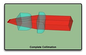
Below is an image I just happen to come across while searching for something else. It resembles what I am trying to accomplish, so I guess it is not a completely novel concept. Thoughts?

300px-LD_Collimation_Complete_view.jpg


Edit:
I may be able to find time soon to perform the experiments that you asked for. Do we know what the focal lengths of the OPT cylindrical lenses are? I have the 2x version for 520nm.
 
Last edited:
Yes. I have a 150 watt CO2 laser for burning and cutting things. My interest in visible handheld lasers is just that, to create the most visible beam at the longest distances physically possible.

In one of our earlier discussions, we hypothesized that instead of starting the optical train with an off-the-shelf 9mm collimator, then using cylindricals to correct the beam shape, then using an expander to lower divergence, one could use an approach that integrates these into fewer steps.

My current plan is to use only two lenses rather than 5-7 as would be the case above. Among other benefits, this greatly reduces reflected power, having a lower number of surfaces. Both lenses will be cylindrical plano convex. One will collimate the fast axis and the other will collimate the slow axis. Since the two axis diverge at different rates, the fast axis collimator will be placed much closer to the diode than the slow axis collimator. This will allow me to collimate each axis at the precise distance such that I have a round/square beam shape.

Further, I will choose a distance for the lenses that also collimates the beam at a diameter that has very low divergence, thus obviating the need for an expander.

I found elsewhere on this forum that 520nm diodes have a 1um x 14um emitter. If we assume this is correct and use the fast and slow axis divergence from the NDG7475 datasheet, then these models below should be quite accurate. Overall, the system consists of: NDG7475 -> PCX -> PCX. It has a final beam shape of 20mm x 20mm and divergence of 0.04 mRad x 0.14 mRad.


Below is an image I just happen to come across while searching for something else. It resembles what I am trying to accomplish, so I guess it is not a completely novel concept. Thoughts?

300px-LD_Collimation_Complete_view.jpg
That's how beams are or can be circularized if one chooses to do so.


This app isn't for cylindrical lenses. Look at the graphic, it assumes one is using common lenses. To model non common lenses you have to use a ray tracing app I beleive.
 
Last edited:


Back
Top