loreadarkshade
Well-known member
- Joined
- Dec 14, 2020
- Messages
- 479
- Points
- 93
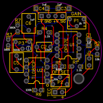
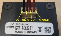
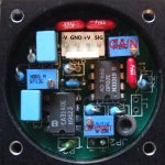
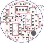
This circuit was directly copied from my Ophir 20C-A-1-Y laser power meter head.
It will provide a reliable analog 1mV / mW output signal from any TEC cell or other sensor.
Calibration will be needed after building the LPM.
I am selling these PCB board kits with all the required components for those of you who don't want to do it yourselves.
$35 + $10 shipping to USA, $20 for international shipping (overseas). Send me a DM or leave a comment.
Please note this circuit is designed for a low output signal TEC.
Using a higher output signal TEC will require changing out R3 to a lower value. (ex. 100k)
The higher R3, the more sensitive the circuit is. the lower R3, the less sensitive the circuit.
Component list:
C1 - 1uF Ceramic Capacitor
C2 - 10nF Ceramic Capacitor
C3 - 1uF Ceramic Capacitor
C4 - 1uF Ceramic Capacitor
C5 - 1uF 63v Film Capacitor
C6 - 1uF 63v Film Capacitor
R1 - 1.126k ohms Resistor
R2 - 8.87k ohms Resistor
R3 - 1.6M ohms Resistor
R4 - 1.208k ohms Resistor
R5 - 391.1k ohms Resistor
R6 - 99.7k ohms Resistor
R7 - 300.6k ohms Resistor
P1 - 2k ohms Trimming Potentiometer - GAIN (Calibrate the LPM)
P2 - 25k ohms Trimming Potentiometer - OFFSET - Zero offset (set LPM to zero with this at thermal equilibrium)
P3 - 500k ohms Trimming Potentiometer - Unknown function
U1: OP07E Operational Amplifier
U2: TL081CP Operational Amplifier (interchangable with CA314OE)
I do not own any rights to this circuit. This is for educational purposes only.
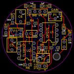
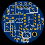
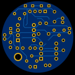


Attachments
Last edited:


