Welcome to Laser Pointer Forums - discuss green laser pointers, blue laser pointers, and all types of lasers

Buy Site Supporter Role (remove some ads) | LPF Donations

Links below open in new window

FrozenGate by Avery

Octuple Red Build

Joined
May 24, 2007
Messages
3,394
Points
0
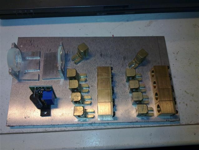
20110204_002Small.jpg


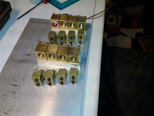
20110207_001Small.jpg


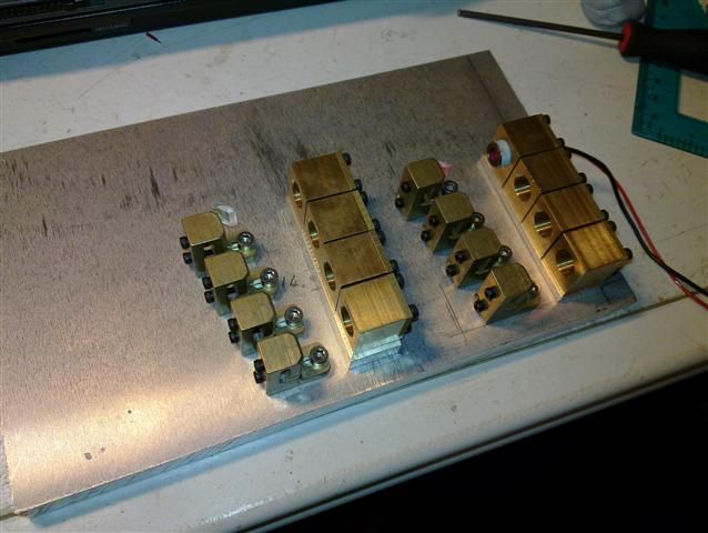
20110207_002Small.jpg


Very impressive indeed.

How long does it take you to get everything lined up?
How are the diodes wired to the driver (series/parallel)?
 
well as i have a milling machine all the holes are drilled perfect so 10-15mins to align.

parallel
 
Hehehe, very nice, very nice.
That a flexmod p3, isn't it?
Mitsubishi open can 660nm?

Might I ask what this will be used in?
A really huge show projector perhaps?
 
yep flexmod p3 driver.

yep LOC open can diode

umm well its only 1.6watts so not a huge projector, but a projector yes. its already sold so i wont be using it.
 
so not a huge projector,
Well just it's red "module" is almost as big as some people's whole projector, so that would be
huge for my (in regard's to projectors, as of yet very) uneducated standards!:)

Perhaps you have a link to pictures of the (not necessarily THIS one) whole thing?
 
Last edited:
huge?

this 8 diode red module is 90mm wide by 190mm long, so far from huge
 
It,s always interesting to see images of larger projects. You learn something from the way each project is set up. This looks good. You said it is already sold, so when you finished the build what was the initial /final beam like as in dimensions and divergence? The telescope seems a little rough, but if you were able to get a good output beam with that level of adjustment that might mean others could as well without over engineering with 5-axis mounts etc. Also the knife edge combiners look only to have tip/tilt and no in/out adjustment. For good final stacking density I assume you set up your steps in drilling the base plate based on a measurement of the width of the coliminated beams? Is that right? Was that difficult? How did you do it?
 
It,s always interesting to see images of larger projects. You learn something from the way each project is set up. This looks good. You said it is already sold, so when you finished the build what was the initial /final beam like as in dimensions and divergence? The telescope seems a little rough, but if you were able to get a good output beam with that level of adjustment that might mean others could as well without over engineering with 5-axis mounts etc. Also the knife edge combiners look only to have tip/tilt and no in/out adjustment. For good final stacking density I assume you set up your steps in drilling the base plate based on a measurement of the width of the coliminated beams? Is that right? Was that difficult? How did you do it?

sold but not completed. but the beam will be 3.5mm by 3.5mm at apeture @1mR
when i finish it ill get some pics up

telescopic - rough?

in and out adjustment on the mirror mounts, i dont get what you mean?
with mirror mounts you only need an up and down adjustment, it makes for a more stable build.

the beam at apeture is 3mm by 5mm, so each hole/mirror mount is set back 3mm from the other.
 
Thanks for the reply. Yes the telescope seems a little rough. The lenses are set on the base plate and only one appears to have slots for mounting screws. The relative position of the two optics seem as if it will be set by sliding each Al bracket and then screwing it down. Any adjustment in tip or tilt to compensate for any astigmatism because the lens is mounted imperfectly seems as if it might be a little challenging. The reason I mentioned about the beam size was that I was uncertain the often quoted 3mmx5mm beam wasn't just an approximation. And if the knife edge mirrors weren't installed consistently on the mounts the ability to tweak the mirror's position after installation might lead to light loss or a larger combined beam. Don't Get me wrong I am raising these issues because I have a tendency to over engineer and waste money/time for minimal benefit. Experience is a great way to decide where to draw the line.
 
Thanks for the reply. Yes the telescope seems a little rough. The lenses are set on the base plate and only one appears to have slots for mounting screws. The relative position of the two optics seem as if it will be set by sliding each Al bracket and then screwing it down. Any adjustment in tip or tilt to compensate for any astigmatism because the lens is mounted imperfectly seems as if it might be a little challenging. The reason I mentioned about the beam size was that I was uncertain the often quoted 3mmx5mm beam wasn't just an approximation. And if the knife edge mirrors weren't installed consistently on the mounts the ability to tweak the mirror's position after installation might lead to light loss or a larger combined beam. Don't Get me wrong I am raising these issues because I have a tendency to over engineer and waste money/time for minimal benefit. Experience is a great way to decide where to draw the line.

the build isnt finished yet hense the telescopics. the telescopics are at a perfect 90 degrees, so the only adjusting you need is back and forth.

everything is perfectly made to be parallel so only back and forth of telescopics i needed.

3mm by 5mm is the beam size of the lens infront of the each diode. all 8 beams combined through the telescopics will be 3.5mm by 3.5mm @ 1mR

ive done this before so am getting very good -

Laser Man - Arctos Multi Diode Array

Laser Man - 1.2watt Sextuple Red Build

Laser Man - 1watt Quad 660nm Build
 
What do you think I might be doing wrong? For my multi-diode red build I am using 4 LPC-815 diodes with Aixiz glass lenses in metal mounts and when focused at 7 meters ( the limit of my room) the spot is 5mm in diameter and quite round. as I measure back to the lens the beam remains 5mm in diameter all the way to the lens ie. no waist. The measurement is made with diode set at a relatively low power (100mw) for convenience and is measured with a calipers set with the jaws just wide enough to just miss the edges of the beam. If this is typical of this diode then I will just have to live with it and increase the magnification of my telescope to fit the combined beam onto the scanner. Are my measurements screwy? Am I over estimating based on scattered relatively insignificant light? Is it this lens? If 3mmx5mm is more appropriate then what might I be doing wrong? I am planning to start machining the diode mounts and the combiner mirrors based on these measurements. Please help.


Back
Top