Welcome to Laser Pointer Forums - discuss green laser pointers, blue laser pointers, and all types of lasers

Buy Site Supporter Role (remove some ads) | LPF Donations

Links below open in new window

FrozenGate by Avery

NUBM31T 95W 455nm

You are getting away with a voltage regulator dc-dc converter because it and your cells can't output enough to hurt the array, you need a current regulator and more battery if you want to get max overdriven output or even the full 95w output, you are likely drawing 9-10a from your cells as they sag under load and your array is likely doing 75w max when it could do 95w rated and 110-125w overdriven if you can keep it cool, but 75w isn't bad if you can hold that 250w output as the cells discharge.
It does have current regulation. There are 2 dials, one for voltage, and the other for current. I wouldn't have used it otherwise.. I have had power sources hooked up to it that can deliver in the hundreds of amps. Also, after conversion I have been able to hold 84 volts 3.3 amps at peak on that laser, which is past it's rating(Also around what Styro was running his at).. Which should mean it should be going past 95 watts. However I turned the current down a bit cause the batteries were getting pretty hot.

And what did you mean about the converter not being strong enough? It can handle WAY past the rating the laser can take. Did you even look at it? :p
 
Last edited:


I would think those arrays could take 4A as long as you can keep it cool, but not with those 8 x 18650, they must need a recharge after a couple of minutes total runtime, how long do you run it ( duty cycle ) ?

Yes 3.0a is 95w by the data sheet so that's a little more efficient than the NUBM08 which can take 4.5a as long as you keep it cool.
I expect the array could do 120w if you can keep it cool.
 
Last edited:
I would think those arrays could take 4A as long as you can keep it cool, but not with those 8 x 18650, they must need a recharge after a couple of minutes total runtime, how long do you run it ( duty cycle ) ?
Yeah I have already ordered a pair of 14.8v high amp lipo batteries. (The Panasonic cells were all I had on hand) In about 8 minutes of straight run time, the laser starts to get a bit more boring. However, it's still far stronger than any hand held laser I've worked with even when the batteries at at zero % haha. also, my small cpu heat sync isnt enough to keep that thing cool at 4 amps. I might make another 'rifle' build where I push the laser hard, with good cooling. Also, I might combine 2 with a prism, depends if I have the time and motivation.

PS, that dc converter can output 600 watts. Pretty nice for $25 CAD
 
Last edited:
Start up ripple could be an issue when you switch to 4s hobby packs, might want to add some caps.
 
I'm currently working on a second 100W laser.
This time I would like to use a lipo battery.
When using lipo, trinh says it's better to use MOSFETs.
The styro 100W laser also used a lipo battery and a MOSFET.
Is this because a large amount of current flows and damages the circuit?
I don't understand the meaning of using MOSFETs.
Please tell me in detail.

A MOSFET is often used for current regulation. The voltage regulator I sent you does exactly this, and it can output more than 600 watts which is triple what the laser can handle. Only with the regulator I sent you, you can directly control and adjust both the voltage and current amount. I WOULDN'T suggest doing what Styro did in his video, unless you have years of experience like him, and you feel confident enough to replicate his design. The voltage regulator I sent you only costs $20 US.

Are you running your NUBM31 in series or parallel? And how are you powering the first one you made? Are you directly powering it with a battery..?
 
Last edited:
A MOSFET is often used for current regulation. The voltage regulator I sent you does exactly this, and it can output more than 600 watts which is triple what the laser can handle. Only with the regulator I sent you, you can directly control and adjust both the voltage and current amount. I WOULDN'T suggest doing what Styro did in his video, unless you have years of experience like him, and you feel confident enough to replicate his design. The voltage regulator I sent you only costs $20 US.

Are you running your NUBM31 in series or parallel? And how are you powering the first one you made? Are you directly powering it with a battery..?
Thank you very much.

The first laser was made by trinh hong, so I'm not familiar with the details.
I need to ask him.

I would like to use the boost converter you introduced.
 
trinh has sent this driver.
I measured the voltage of this driver.
The voltage is 94V.
I think this voltage is high, so is it dangerous to use it with the NUBM31T?
I don't think it's good to use this driver.
However, the first laser uses this driver.


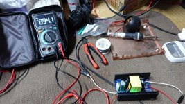
DSC01204_result.JPG
 
trinh has sent this driver.
I measured the voltage of this driver.
The voltage is 94V.
I think this voltage is high, so is it dangerous to use it with the NUBM31T?
I don't think it's good to use this driver.
However, the first laser uses this driver.


View attachment 72737
94v open circuit doesn't mean much for an unloaded boost converter. Member Light superglue generously sent me 2 for testing: I have this much to say since I don't have an appropriate load but I am looking into that:
Open circuit voltage is 94V
The component quality is what is to be expected from a cheap mass-produced Chinese product: very bad
On the back of the board, there are a lot of cold solder joins
It seems to be doing actually CC, Adjusting the pot didn't vary the voltage, and there seems to be a 50milliohm resistor they use to do 4wire kelvin probing for determining the current, Ic itself seems like a generic boost CV controller, they are using a current sense amp to add CC functionality to that. Topology is most likely flyback with an aux supply. FYI L1 is nothing but a jumper for the -.
 
A MOSFET is often used for current regulation. The voltage regulator I sent you does exactly this, and it can output more than 600 watts which is triple what the laser can handle. Only with the regulator I sent you, you can directly control and adjust both the voltage and current amount. I WOULDN'T suggest doing what Styro did in his video, unless you have years of experience like him, and you feel confident enough to replicate his design. The voltage regulator I sent you only costs $20 US.

Are you running your NUBM31 in series or parallel? And how are you powering the first one you made? Are you directly powering it with a battery..?
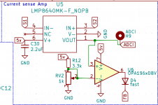
A MOSFET isnt often used for CC wtf, today we use either dedicated ICs with internal current sense circuits or a normal CV switching controller upon which we add the CC function by tapping the feedback loop with a circuit like this( found in my open-source power supply) 1621518882092.png
 
It does have current regulation. There are 2 dials, one for voltage, and the other for current. I wouldn't have used it otherwise.. I have had power sources hooked up to it that can deliver in the hundreds of amps. Also, after conversion I have been able to hold 84 volts 3.3 amps at peak on that laser, which is past it's rating(Also around what Styro was running his at).. Which should mean it should be going past 95 watts. However I turned the current down a bit cause the batteries were getting pretty hot.

And what did you mean about the converter not being strong enough? It can handle WAY past the rating the laser can take. Did you even look at it? :p
I wouldn't recommend it, as Implied by the heavy use of electrolytic and sub-optimal layout, that supply reaks of Chiniseum and low switching frequency with all the other nasty stuff like high ripple, ringing so high the devil can hear and output capacitances bigger than my future.
 
I wouldn't recommend it, as Implied by the heavy use of electrolytic and sub-optimal layout, that supply reaks of Chiniseum and low switching frequency with all the other nasty stuff like high ripple, ringing so high the devil can hear and output capacitances bigger than my future.
I'm pretty amature with electronics. But this device seems to work really well so far. If you are looking for something cheap, flexible and high power it works? One guy did a review on start up current surge on the device, and said it was actually minimal. I haven't noticed any bright flicker in the laser when it's switched on, but then again it might be so brief it can't be seen. Besides, as long as the voltage is low enough, would a millisecond of high current even have any effect? Laser diodes resist current on their own until they heat up...

Are you just assuming the device has faults cause it's cheap? Or have you actually worked with it? I'm not defending it's 'honor' I'm just wondering. :p You don't like the one sold on ebay or my suggestion on amazon, so you aren't even giving any options here haha to toutan. "Everything is bad, don't buy anything!" :p You're not really helping anyone here.

@toutan 94 volts is not too high if you're wiring the laser array in series. You need to make sure to wire each pin on the array in 'series', this brings the voltage up, but the amps down. If you don't wire in series, the laser will require really high amperage, and you will have big problems feeding it 94 volts if they are in parallel.
 
Last edited:
I'm researching MOSFETs in various ways.
The reason for using MOSFET seems to be to protect the switch.
Sparks occur because a large current flows when the switch is turned on.
I got the information that MOSFET is used to suppress the generation of the spark.
Is this the correct way to use it?
 
How to connect the drivers in series and in parallel
Specifically, what kind of connection is in series or in parallel?
I'm confused.
 
How to connect the drivers in series and in parallel
Specifically, what kind of connection is in series or in parallel?
I'm confused.

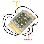
Yeah sorry, I was mixed up with MOSFETs and the LM(Linear regulators). I drew this up for you. I wouldn't worry too much about MOSFETs, I am using a 'microwave door' button switch, which can handle 10 amps.

These aren't the exact ones I'm using, but they are all over the place: https://www.amazon.ca/Twidec-Univer...jbGlja1JlZGlyZWN0JmRvTm90TG9nQ2xpY2s9dHJ1ZQ==

This is 'series' wiring. With this configuration, the laser wont even turn on until somewhere in the 60 volt range. but the amperage will be nice and low.

serieswiring.jpg
 
Last edited:


Back
Top