Welcome to Laser Pointer Forums - discuss green laser pointers, blue laser pointers, and all types of lasers

Buy Site Supporter Role (remove some ads) | LPF Donations

Links below open in new window

FrozenGate by Avery

NJG-18, multimode boost driver for 445nm.. and possibly 650nm

Um. Are you talking about a modflex or a microflex? SMD capacitors seldom have stripes.. much less two lines of text. heh. Your lucky when you get 3 digits on them.


the output cap is the black thing with a white line on one side and it theres two lines of reading 100 and 6V. you usually blow the cap when theres power applied to the driver without a load.
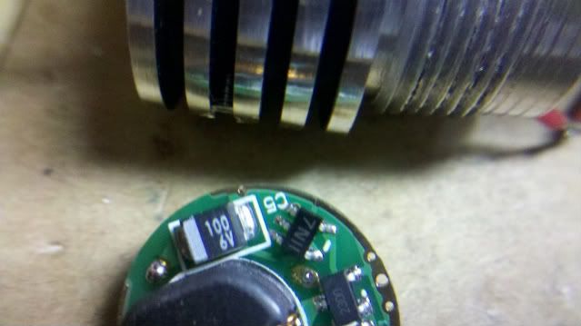
Ok. Ill take a look when i get home. And thanks for all the help. Is there any further news when dr lava will be selling the v5 again? Heard they were suppossed to be in stock soon.

Edit: OK I looked for it but I am either blind or it is no longer there. What side is it on, the side with the pot or the side that needs to be soldered?
 
Last edited:
You have a micro flexdrive.. It's not going to have a capacitor on it resembling what steviedezie is describing. I think he's talking about a modflex.. which is an entirely different.. and much larger, driver all together.
 
I believe the component stevie is talking about is on the NJG-18. He describes "black thing with a white line on one side and it theres two lines of reading 100 and 6V"

2011-05-10_00-31-25_54-1.jpg


I see it!!!! :D

Isn't that a diode, anyway?
 
Last edited:
Ok. Well that makes more sense now. So does anybody might have any idea as to what got blown when the load gets disconnected on a micro flex v5
 
Ah. Well I know the micro flexdrives don't have SMD caps near that size on them. Though generally, IMHO.. Normally it's not cost effective to repair them. Though seeing as you can't get them at the moment.. That makes things a little different. Though I still bet it's not as simple as a dead capacitor. Unless the capacitor ends up shorted.. It should still work if it's an output capacitor.. You just lose some filtering. My guess is the regulator fried itself by ramping up it's voltage trying to get the current to increase.
 
Yea I tried to find anything noticeably wring with it but to no avail. Well looks like im waiting till someone gets more in stock...Thanks for all the help!
 
i ordered a bunch from kaidomain a while back when e-lectronics.net first went out of stock, and they finally got here. I noticed that the kaidomain has the blue boards while e-lectonics.net has the green boards. THey are the same component wise, but the kaidomain ones have the C1 brigde already done. I dont particularly like that...it makes it harder to securely solder the output + wire... i usually like my leads to have solid solder on both sides of the board...but since the kaidomain boards have the c1 brigde, the hole for the + lead is full of solder, and the solder sucker cant get all the solder out...ohh well. aside from that its all good.
 
Strange. I just got an order of 20 from Kaidomain last week. All the boards are green, the C1 is not soldered and there is not solder in the holes.:thinking:
 
very strange indeed. i get the a slight feeling the blue boards are a bit smaller than the green boards...my mircometer shows .14mm difference on one and .18mm on another...it fit into qumefox's host without sanding down...while the green boards required a bit of sanding...
 
Hmmm. My green ones from e-electronics fall right into the step on qume's host. I actually have negaive contact problems because of this. The lack of press fit doesn't give the edge of the board enough negative host contact. :( I got my new CU one today, so well see how the driver fits in that one.
 
Hmmm. My green ones from e-electronics fall right into the step on qume's host. I actually have negaive contact problems because of this. The lack of press fit doesn't give the edge of the board enough negative host contact. :( I got my new CU one today, so well see how the driver fits in that one.

Almost never will - you pretty much always need to bridge the edge and the host with a bit of solder (a wide bridge, and hopefully in multiple positions around the edge).
 
Almost never will - you pretty much always need to bridge the edge and the host with a bit of solder (a wide bridge, and hopefully in multiple positions around the edge).

Really? Every time I turned out a sink with a press-fit driver, they always had excellent negative pathway contact. No solder mounds on either side. Just pressed in nice and flush. Maybe it has to do with how tight of a tolerance I bore for the press-fit.

Also, how would I solder it to the host? The driver mount is aluminum. You cannot solder to AL very well. I turn a brass ring that presses into the sink when I want to do that. :)
 
Last edited:
I can guarantee that the diameters of the PCB notch are all within .008" of each other on all the heatsinks.. . The problems come from diameters of the drivers varying. And yes. Some type of decent negative connection should be made to the heatsink.. Though usually putting solder blobs on the four side pads (at least of the stock PCB I ship them with) before pressing them in is enough. I haven't done any builds with these myself using a NJG-18... yet. But I probably will as soon as I get more 445 diodes.
 
Last edited:
i never tried this with lasers, but for flashlights, i take the brass pill and clamp it in a vice and bust out the pen tip torch, i wait like 5-6 seconds and then i dab the edges with solder... the solder sticks to the aluminum like glue. i do this in several places around the pill then when everything is cool i press the driver in and add solder bridges to the driver negative ring and those lil bits of solder on the pill... I cant turn out stuff on a lathe so thats the only way i know to get a good solid negative connection when the driver is loose in the pill.
 
Last edited:
I need help, guys.

For last two hours, I'm pulling my hair over this NJG-18 cr*p.

Purchased off Kaidomain two pieces, both are green boards and have visible trace connecting the "fix" from first page here.

First one literally exploded during test setting. Capacitor blew itself in half. No other components appear damaged though. I replaced capacitor and put it all away for a minute, I went to test the other one.

So I have it all encased in laser host, just that where beam was supposed to be coming out, I have my test load.

Now, first of all, which turning durection increases-decreases output current?
Second, maximum output declated at 3A on DX - under which circuimstances?
Can one overshoot the trimmer and blow a 445nm diode off? Because I'm aiming at some 1.2 A as described up there, is it possible it goes over it?

Second, what the heck with all these stupid damned modes?!
I have been clicking and tapping the damned clicky for last two hours in futile attempt to get one stable usable reading off the test load.

It just simply jumps around, no constant mode anywhere, as if I'm stuck in all those pointless pulsing modes. Also, very high pitched whine coming from driver inside host, barely audible.

So would somebody help me with this current setting? Most appreciated would be a picture of the set trimmer on driver preset for 1.2 A for 445nm.
If not, then somebody tell me how does one change those stupid modes, and what's the actual current range of the driver.

Would be much appreciated. Thanks :)

P.S.Vent.off. If there's one thing I hate more than randomness of damned trimmers and pots, that's the randomness of some gazillion different modes which one accesses through the button used to turn the flashlight on. Seriously this is worse than the SmartSwitch from G2. How the hell am I even supposed to know which mode am I measuring?


Back
Top