Welcome to Laser Pointer Forums - discuss green laser pointers, blue laser pointers, and all types of lasers

LPF Donation via Stripe | LPF Donation - Other Methods

Links below open in new window

ArcticMyst Security by Avery

need help with repairing/rebuilding a Laser please :)

Mannitu78

Member
Joined
Dec 19, 2019
Messages
92
Points
8
Hello friends.
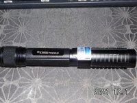
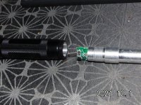
few weeks ago my 1600mw blue laser went down. It was a prebuild Laser for 50eu from china and actually quite decent. The diode suddenly only put out half its usual power, also the spot looked weird, not like it always did. Tried different batteries, no sucess. Now i want to take the chance to finally put something together, something i nerver did, but i bought a bunch of stuff already 1 or 2 years ago, different parts, diodes, soldering iron etc.

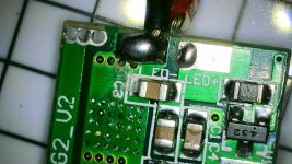
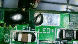
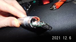
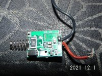
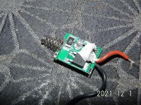
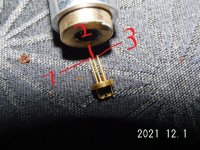
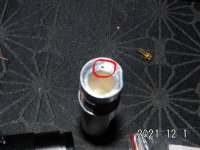
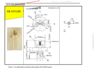
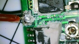
So i managed to tear that thing down which wasnt quite easy, now i basically just want to put in a 400mw red laser diode from Mitsubishi i think. Have 2 points of concern now, 1 is soldering the cables to the right spot/pole, 2 is turning down the potentiometer on that driver. I want to reuse it, i hav another, probably better one, but its to large for that casing. The previous diode was 1600mw so i will have to turn it down...anybody has an idea how to proceed, so i can make sure not to destroy the diode but also not run it way below what it can handle? here are some pics, if anybody needs a better or bigger one i will try to deliver, its just always a pain with this very small sized pics.


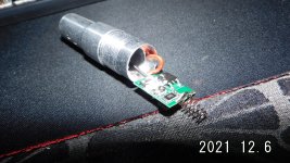
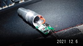
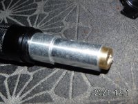
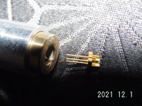
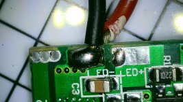
edit: i just realized 2 things, 1 the red-brown cable on the driver, it is so short, it cant even reach the diode through that aluminum cylinder. Is it possibly that it must be put into that very small hole? i marked it on the last foto. Im really a noob so this is all just guessing. That would mean that only 1 cable, the black one, reaches the diode? But why does it have 3 contacts then? Hmm
 

Attachments

  • DSCI1581.JPG
    DSCI1581.JPG
    228.3 KB · Views: 9
  • DSCI1582.JPG
    DSCI1582.JPG
    215.3 KB · Views: 8
  • DSCI1583.JPG
    DSCI1583.JPG
    227.2 KB · Views: 10
  • DSCI1585.JPG
    DSCI1585.JPG
    217 KB · Views: 10
  • DSCI1589.JPG
    DSCI1589.JPG
    209.8 KB · Views: 9
  • DSCI1591.JPG
    DSCI1591.JPG
    214.4 KB · Views: 9
  • DSCI1593.JPG
    DSCI1593.JPG
    204.7 KB · Views: 8
  • DSCI1602[1].JPG
    DSCI1602[1].JPG
    219.5 KB · Views: 8
  • DSCI1601.JPG
    DSCI1601.JPG
    258.3 KB · Views: 7
Last edited:


Mannitu78

Member
Joined
Dec 19, 2019
Messages
92
Points
8
nobody can help me?hm..
i digged out the diodes info, to my surprise its only 400mw pulse, not 400 constant output. However, i really want to make this work, before i go ony building more expensive stuff. I dont even understand that drawing, can someone show or translate me that, what about this 3 pin, what cables to connect? As far as i understand from the teardown of this laser, the driver had 2 cables from which only 1 connected to the diodes pins. Athe second cable went into the casing, it seems it connects to the diode from touch, but not over the pin. That means that from the 3 pins on the diode, only 1 gets a cable attached?

Im really desperatd :(
 

Attachments

  • Unbenannt.PNG
    Unbenannt.PNG
    192.9 KB · Views: 10

Anthony P

Well-known member
Joined
Oct 7, 2018
Messages
529
Points
63
It looks to me as if pin 2 is not used at all. Pin 3 is negative and case, so a single + wire to pin 1 and case ground should work.
I would use a test load and figure out the driver.
Hope this helps.
 

Mannitu78

Member
Joined
Dec 19, 2019
Messages
92
Points
8
you said " a single+ wire to pin 1 and case ground should work"..that confuses me a little bit, does that mean i should pull a cable from + on the driver to pin 1?
I guess the red cable from the driver goes to case in any way, right?


this are 2 supercloseshots from the driver. It looks like the black cable is soldered to "ED -" "ED +" next to it is free, but on the other side, it seems theres also a single "ED +" printed and thats where the red cable is attached..

so you think i should desolder the cable from "ED -" and solder it from "ED +" to pin 1? That means i would have to solder the red cable from "E -" to case?

thx for your help
 

Attachments

  • WIN_20211204_03_28_47_Pro.jpg
    WIN_20211204_03_28_47_Pro.jpg
    176.2 KB · Views: 6
  • WIN_20211204_03_52_45_Pro.jpg
    WIN_20211204_03_52_45_Pro.jpg
    165.8 KB · Views: 6
Last edited:

Anthony P

Well-known member
Joined
Oct 7, 2018
Messages
529
Points
63
I do not have it in my hands to be certain. It looks like red is ED+ and goes to pin 1. I would solder the black ED- to pin3. Optionally, ED- can connect to the case of the diode through a mechanical connection between diode module and black wire. I would connect a test load to the driver and verify everything before moving forward. Did that driver have a separate - input from battery or is ED- common? Also, that is an open can diode you have. I would get it pressed into module and cover the output end of module with a lens or at least a piece of tape. ESD is important in handling any diode. All diodes are fragile and sensitive, but open cans more so.
 

Mannitu78

Member
Joined
Dec 19, 2019
Messages
92
Points
8
i already checked everything, it fits into the aluminummodul from the original blue laser. I know i cant heat it up without heatsink.

edit:
if you look at one of my pics above, i laid the driver next to the modul it stuck in, you can see only the black cable is long enough to reach the diode, the red went inot the side of the module, theres even a tiny hole drilled into it. The question is, why did they do that, why didnt the make the red cable 2 inch longer an solder it regularly to the diode? Is it maybe because the driver needs this connection to the case to get the power from the batteries? Because i can see only 1 connection, that is the spring, so there needs to be another?

thx


edit, lol, 20 minutes later i understand your question
"Did that driver have a separate - input from battery or is ED- common?"
yeah its what i tried to explain. No it doesnt have any other connections, i tried to lay the parts in the pics so you can see exactly how the laser was built together. Driver only had 3 contacts, one cable to the diode, one to the module/case and then the spring at the bottom of the driver. I guess the spring is negative, because it touches the flat side of the battery and that is negative in my case. I guess its always.Thats what made it difficult for me to understand. It seems like the red cable is used for 2 different "cycles"? however, once to power diode and another to power driver.


i have 2 of this diodes. They were dirtcheap, i think 5 or 6eu for 2 pieces. I bought them for this reason, to practice my 1st build/mod. However if i saw that they had 3 pins, i wouldnt have bothered, this is so much extra-confusion for an electronicnoob :)
Also they have only 150mw but were promoted as 400mw. I guess you have to search the specsheets in every case.


PS:
i will try to summerize what we got so far:
-on this diode, pin 3 is negative and can be run through the case.
- it seems with old diode, thats in trash now, that positiv was run through the case. Because the red cable is positiv and stuck into the case.
-now if i make the red cable longer and connect both + and - on the diode the usual way, theres the problem that the driver has no power-cycle, right?
 
Last edited:

Mannitu78

Member
Joined
Dec 19, 2019
Messages
92
Points
8
man, something just came into my mind. I think there WAS another cable soldered next to the black. There is a bump of tin-soldier as you can see and i dont think it came that way from the factory. Isnt that flat usual? Heres the thing: i dont remember if there was something on the diode, i just pulled it out and thre it away. I think that clears things up? Or maybe it wasnt? the hump at the black cable is so much bigger than the small one...

sorry for making you read so much ineffective word.
 

Attachments

  • WIN_20211205_20_07_27_Pro.jpg
    WIN_20211205_20_07_27_Pro.jpg
    189.8 KB · Views: 4
  • WIN_20211205_20_13_59_Pro.jpg
    WIN_20211205_20_13_59_Pro.jpg
    232.8 KB · Views: 4

Anthony P

Well-known member
Joined
Oct 7, 2018
Messages
529
Points
63
Noticed that ED+ and ED- are actually LED+ and LED-.
Use your VOM and see if you have continuity from spring to LED-. That board had to contact the sides of the case somehow to get power. Are you sure the battery went in with - to the spring? Does it use a tail cap switch ? What holds the board in place?
 

Mannitu78

Member
Joined
Dec 19, 2019
Messages
92
Points
8
if you look at my pictures above, you will see a tiny hole drilled in the wall of the modul, its red circled, thats where the red cable stuck in. makes sense, thats why there are 2 times positiv on the board. Diode + and - are one one side of the board, Driver + is on the other side. driver - is spring. The only thing im not sure of is, if there was another cable from the LED + to the diode, my feelings say no, but that little bump makes me think, how does that look to you on LED+, does it look like there was a cable to you?


There def. was no other connection from the board to the batteries.

what holds the board in place? Just look at my pics above. You can see step by step how the laser was teared down. The third pic, or DSCI 1583, you can see how it was pressed into one side of the aluminum laser module. And secured with a bit of sgrey silicon..black cable went through the module to the diode and red cable was in the tiny hole drilled into the module.
It uses a tailcapswitch, yes.

And yes, the flat side of my batteries are def. neg, the button side is positiv.

I have no voltmeter anymore..i bought one, also a year ago but on one point i tried to repair an electro-roller from a friend and it blew up when i tried to "check if the battery pack is still ok"...XD

do you think its possible that both driver/battery and driver/diode circuits run through the case without "interfering with each other"? Is this normal for diodes, that you can solder only 1 cable and the other pole is just created by pressing it into the module? That means that it has a direct connection to the battery without driver in between? man thats so confusing.


added some pics, hope that clears up how the driver is fixed. Later it will be pushed in half the way and the gaps between driver and board are filled with silicon. at least one side.

Man i hope ill learn soon how to deal with this things...im really looking forward to build some serious lasers..i could build a 5W laser so cheap...but i dont like potentiometers. I will only buy drivers that are not capeable of putting too much power into my diode.
 

Attachments

  • DSCI1603.JPG
    DSCI1603.JPG
    553.3 KB · Views: 4
  • DSCI1604.JPG
    DSCI1604.JPG
    541.6 KB · Views: 4
  • DSCI1605.JPG
    DSCI1605.JPG
    537.5 KB · Views: 4
  • DSCI1601.JPG
    DSCI1601.JPG
    258.3 KB · Views: 4
Last edited:

Anthony P

Well-known member
Joined
Oct 7, 2018
Messages
529
Points
63
So your driver is configured for case positive and your new diode is case negative. This means that your diode and module will have to be insulated from host. You are really going to need a simple VOM ($10.00 ) and a test load ( <$5.00).
 

Mannitu78

Member
Joined
Dec 19, 2019
Messages
92
Points
8
yeah i guess ill order a new VOM...the one i had was pretty nice, was 20 bucks. I dont even know what you mean when you say "test load"? Is that a device? So you say both diode and driver can only be run through the case if its same polarity?

PS:
so, i just inspected the "rest" of my Multimeter, seems its still working, just the test probes are kind of...molten?...already ordered some new probes for 7 bucks. I tried to look up "test load" on ebay, it keeps showing me devices for 150eu. What am i supposed to do with that thing?

also learned something about Multimeters, it seems both my 250ma and 10A fuses are broken, already ordered new ones. I tried to hook a battery on the driver and then check if the potentiometer on the board is working as it should and realized the Multimeter works on everything but not on Amp/current. Makes sense after what i tried on that Electroroller. happy its still working though.

maybe you ask yourself why i dont just order a better Driver and diode, thing is i really want to learn how to get things done. I even have all kinds of stuff here on drivers and casings, also ordered some copper casings for 9mm diodes, because the good highpowered diodes from Nichia seem to be 9mm.
But i would really appriciate if i can get this little crappy thing to run.
 
Last edited:

Anthony P

Well-known member
Joined
Oct 7, 2018
Messages
529
Points
63
A driver should never be powered up with no load. Instead of using you expensive and fragile diode as a load, you can use a string of 3 or 4 cheap 1n4001 diodes in series with a 1 ohm resistor to simulate the laser. 4001s are good up to about 1 amp. If you google "laser diode test load" you will find tons of info.
 

Mannitu78

Member
Joined
Dec 19, 2019
Messages
92
Points
8
ok, ill order the diodes and resistors from this diagram, ok? i should be able to test everything up to 5A, right? Not sure how to build this and where to put my Multimeter probes yet but ill find out XD
 

Attachments

  • Unbenannt.PNG
    Unbenannt.PNG
    37.9 KB · Views: 9

Mannitu78

Member
Joined
Dec 19, 2019
Messages
92
Points
8
i have 2 question please:
1. For my testload, i need a 1 Ohm resistor, can i buy a small potentiometer and set it to 1 Ohm for that purpose? I imagine such a thing would be useful, better than ordering tons of resistors in the future.

2.the cheap testload, with the 1N4001:
I dont quite understand where to put my Multimeter probes, once i hokked this up to my driver.
I says "put your probes on current monitor and ground pin"..i dont think i have those pins or reading points on that shitty little driver. What now?
 

Anthony P

Well-known member
Joined
Oct 7, 2018
Messages
529
Points
63
If you want to test up to 5A, then your diodes must be rated for 5A or more, and a high watt resistor. Mouser Electronics has everything you need.
I like to use 3 diodes and 1 Ohm resistor. With test load connected to driver, place volt probes on each side of resistor. Bt Ohm's law, 1V on meter = 1A of current.
At 5A, I would worry that a pot would burn.
 

Mannitu78

Member
Joined
Dec 19, 2019
Messages
92
Points
8
well, ill take the 80sq030s for the 5A version...and a 0,1Ohm resistor at least 5 Watts. Yes, about the potentiometer, they name only Ohm-Range and Power in the specs, no current. Ill see what potentiometer i find, they are cheap. But it would work like a normal resistor, if i turn it to the right resistance?

And you say, just put the probe clamps left and right from the Resistor/Poti? Well thats pretty straight forward i think i will be able to get that done.

I order everything from aliexpress, its free shipping to Germany most of the times, even if you buy only for 2eu XD

Ah yes, i more thing please, in the PNG i posted about, with the 2 schemes of the test load, it says "1,5v-2v Compliance"? what does that mean? that the actual voltage that comes out of the driver must be in that range? shall i hook 1 battery to the driver, or both, that would be real-usecase scenario? Those batteries are about 4V each. Im not sure if that makes a difference on the drivers output, i also dont know the output voltage on that driver.
 
Last edited:


Top