Welcome to Laser Pointer Forums - discuss green laser pointers, blue laser pointers, and all types of lasers

Buy Site Supporter Role (remove some ads) | LPF Donations

Links below open in new window

FrozenGate by Avery

NEC GLS-3030 Argon ion restoration questions

It's odd, as there's no need for what they did, are you sure it's a prism though, not a turning mirror in there? The multiple dots are from mirror wedge, and yeah it's a pain. Makes me curious as to why yours is set up so odd. I had a few words with Sam about it, and he needs a bit more information from you about it so I would definitely shoot him an email. I sent you a PM with his information. Maybe he can offer you some additional advice. There's got to be a quirk here we're not seeing. Cheers!


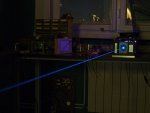
Success :) :) :) I got the 514nm line! I repeated the He-Ne procedure outlined in my previous post to utmost precision, this time adding a few additional checks and carefully paying attention that my adjustments are carried out in such a way that the process is well convergent. After 3 hours of fiddling I finally powered the tube and after just a few nudges of the prism screws I got a green beam. There was not enough travel of the prism tilt screw to get the 488nm line, but this is now easy to fix once I know that I got the OC set correctly, and I can play with the prism alignment without loosing the beam.

My assumption was correct, the HR is on the prism side (cathode), the OC is on the anode side. The alignment is done from the prism side, and if carried out correctly, the alignment of the OC will be wavelength independent. When I finish with this I plan to write a detailed instruction manual with photos for this type of setup, I will also send it to Sam so that he can include it in his FAQ.

It's almost 1:00AM here in Belgrade now, I think it's time for some sleep :)

514 would make sense. its the brightest argon line (not 488) and as you said the mirror was reflective at green. I doubt it does both, its not likely designed to do both wavelengths, but that would depend on the mirrors a lot. Its a small low power argon, and not really meant for heavy duty cycles as far as I know.
 
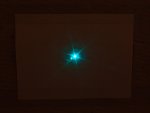
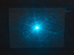
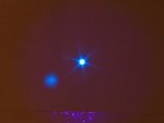
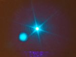
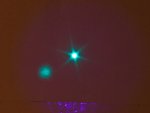
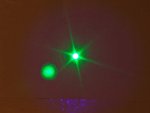
More mysteries - I set the prism travel correctly now and got the blue line, but I also got another unexpected green line! In the pics it is Line1, it is relatively close to the strongest one (Line2 - I assume this is the 514.5nm), and further away I got a blue line (Line3 - I assume this is the 488nm). Or am I wrong?

The exposure on all photos is the same so the intensity is comparable, and white balance is set to Daylight, can anyone recognize Line1 and confirm the others? Maybe this is not a pure argon tube, or I did not identify these correctly?
 

Attachments

  • Line1.jpg
    Line1.jpg
    80 KB · Views: 63
  • Line2.jpg
    Line2.jpg
    164.3 KB · Views: 73
  • Line3.jpg
    Line3.jpg
    80.8 KB · Views: 66
  • IMG_6567.jpg
    IMG_6567.jpg
    108.3 KB · Views: 77
More mysteries - I set the prism travel correctly now and got the blue line, but I also got another unexpected green line! In the pics it is Line1, it is relatively close to the strongest one (Line2 - I assume this is the 514.5nm), and further away I got a blue line (Line3 - I assume this is the 488nm). Or am I wrong?

The exposure on all photos is the same so the intensity is comparable, and white balance is set to Daylight, can anyone recognize Line1 and confirm the others? Maybe this is not a pure argon tube, or I did not identify these correctly?

Going by your pictures your third line looks more like the 457nm line to me. Cameras can be deceiving though.

The 514nm line should be a nice forest green, which I can see a hint of in your first picture (The speckle/splash around the outside looks green to me), although the dot looks more blue. Maybe 496nm? The second picture looks more like 488nm to me, given the colour and intensity. Line 3 I'd say again is 457nm.

Really difficult to tell from pictures unless you have the lines side by side all at once. :(

Great job getting it going! :D :D
 
Last edited:
Solved by measuring the prism tilt angle and rough intensity estimation, the lines from my previous post were 476.5, 488 and 496.5. I reconfigured the prism mount once again and got the missing 514.5, now I have enough travel to adjust for any of these. 488 is the brightest, not the 514, it seems that the mirrors were optimized for 488. I'm more than happy with the result, 4 lines at less than 6A, I guess this tube still has some life left in it.

I'd say the most important part of this restoration is now over, thank you all for your support and feedback :) Next I need to make a proper cover for this head and tidy up the current control electronics...
 

Attachments

  • 476.5nm.jpg
    476.5nm.jpg
    107.2 KB · Views: 43
  • 488.0nm.jpg
    488.0nm.jpg
    156.6 KB · Views: 44
  • 496.5nm.jpg
    496.5nm.jpg
    111 KB · Views: 53
  • 514.5nm.jpg
    514.5nm.jpg
    123.3 KB · Views: 54
Congrats! glad you got it working. I imagine it was only meant to do 488, and the prism was likely meant to keep the other lines from oscillating as insurance. (i've seen some HeNes designed the same way) or to manually allow different line uses as a basic tunable. i'd assume the former more likely. Sounds like the mirrors are definitely suitable for a variety, as those are all 4 of the major argon lines. but you're right it sounds like the mirrors and gas pressure are intended for the 488 setup. the 501 and 457 lines are far lower gain, and a bit harder to get, but maybe you'll see them at some point too depending on how the laser is setup.
 
Your cathode is running off AC correct? You might want to rig the center tapped feed so that the plasma is balenced evenly on the cathode, failure to do this results in a drastically shortened cathode life.

Steve
 
LSRFAQ:
Your cathode is running off AC correct? You might want to rig the center tapped feed so that the plasma is balenced evenly on the cathode, failure to do this results in a drastically shortened cathode life.

Steve

You may be right, good topic, definitely worth discussing.

No, currently I'm running the filament using a regulated DC SMPS with a gentle voltage ramp on start-up to handle the cold filament. Positive end towards the bore. I don't have the center tapped transformer + variac to control the voltage, to much hassle compared to the elegant and efficient SMPS :)

I'm wondering why the DC approach should be so hard on the cathode:
- Both thermodynamic and electric properties of the plasma should cause it to spread widely inside of the cathode bulb (hence the large purple cloud we see on the photos), so the flow of ions should spread on the cathode more evenly, not only to the front side facing the bore/anode.
- The mere 3 volts on the filament are really not that much compared to the approx. 90V of the anode voltage. And if the polarity is set with positive end at the front terminal, the back part of the cathode should be stimulated. Many direct heated electron tubes run with even higher filament voltages (up to 20V) creating quite an imbalance towards the control grid, and require DC power to avoid interference with the signal.
- The construction of the cathode implies a strong temperature gradient along the filament coils, the central point is much hotter than the terminals. So the colder terminals must inevitably take all the bashing from heavy ions, regardless of the DC or AC heating. The electron space charge area should be of very small dimensions (less than a millimeter in thickness IIRC), so the hot central part cannot provide much help to the outer colder parts. Or not?
- I'm not even sure which type of cathode this is, thoriated tungsten? For sure it does not look like an oxide one, and I suppose the ions would erode it quickly. Either way to my eye it looks a bit too cold for a bare metal cathode (thoriated tungsten should be run between 1900-2050K).

Suggestions, comments?
 
One, its not an oxide cathode by any means.. Always Barium Dispenser. Oxide cathodes only last a few hours in ion laser service.

Your full answer is contained in Halsted, A Bridges, W Manufacturing Methods Program Five Watt Ion Laser, Volume One Which is probably a bit hard to get outside of the US. It's a US Air Force Document, on a muti-year research program which sped the Ion laser to commercial sale.

What is not readily appearent to the naked eye is a ion sheath formed just past the cathode dark space in the plasma. A 3 volt AC field is enough to move it around, but a DC field pulls it to one side and into contact, causing energetic, localized Ion bombardment. That selectively etches the cathode near the joint to the feedthru lead.


Generally cathode lifetime with a DC field is a few tens of hours before serious erosion starts. Failure is typically within 50-80 hours of operation on DC.

Which is why the low noise lasers operate their cathode on DC with the field flipped about ten times per second to even the wear.
There have been very few of them made, the reduced lifetime means that the factory warrenty is frequently used by the customer.


I received a phone call a few years ago from an instrument manufacturer who wanted rid of 50 and 60 Hertz amplitude noise in their semiconductor wafer mapping instruments, every cathode they ran on DC died within 24 hours.

JDSU then contacted me, and were getting less then a week on the 24 tubes they placed on DC cathode life test. For essentially the same reason, reduction of amplitude noise.

I know of another manufacturer who redesigned the bore to cathode distance to eliminate the effect by changing the dark space distance. However it really lengthened the tube, which is not the case with the NEC, and I used to have quite a few NECs.

The DC erosion starts at one end, and typically occurs just past where the nickel or molybednum plate or tube is tig welded between the tungsten lead and the braze to the Kovar lead. This is the weakest point of the cathode structure. The intermediate metal is there because typical braze and lead materials alloy with the tungsten and mechanically weaken it, when hot.

In the first two cases, I sited Bridges and Halstead, and told them to test for a reversal rate that stopped the erosion. The third party was well aware of the problem and had an alternative solution to it, but still at a greatly reduced lifetime and increeased tube length.

If I have time to scan in Bridges and Halsted, I'll do so, but suffice it to say, heed my warning for now. This has been a known problem since the invention of the ion laser.

There is no reason to soft start the cathode, in fact we avoid it, as the tungsten core has a well known soft phase at about 700' C during warmup. Sagging or shorted turn cathodes are typically caused by two reasons, a low tube fill pressure causing localized plasma heating, and/or a misadjusted cathode transformer where the cathode is too cold.

Some larger lasers do run constant wattage AC transformers, but even those surge the cathode till it self stabilizes at operating temperature. Lasers that do not have ferroresonant transformers, have tapped transformers for the cathode, set by the installation
engineer. The factory produces a tap chart for each model.

A few JDSU models have switching power supplies for the cathodes that supply high frequency AC. It reduces the weight of the PSU.


Laser cathodes are ran cold, typically ~1150 Deg K..., orange hot to barely white hot.

Its been about five years since I've had to explain all this, so my explation may be a bit rusty.

The plasma sheath interaction is complex, I can guage the health and gas pressure of a tube by how the delta in the cathode heating current behaves when the plasma starts, and transitions to a stable arc... Removing electrons properly cools the cathode, so we see a positive delta in a healthy tube. Ion bombardment from improper pressure does the opposite. A middle of life tube shows low or no delta.

The effect is so pronounced, that factory tube test sheets , show plasma on, and plasma off cathode tests.

Gas is driven into the tube walls during operation. If everything is perfect, your NEC would become hard starting from low gas pressure at end of life. The cathode would then fail from ion bombardment, and loose its emissive surface.

The huge NEC end bell is there as a gas resivoir to stabilize the pressure for long life.. A larger laser would have a seperate tank attached, or has a solenoid valve system for gas fill.


DC operation would be desirable, but with a few tiny exceptions, all mass produced ion lasers have balanced, ac cathodes, with the DC current fed to the center tap of the cathode transformer.

Please heed my warning, but it would be three or four days before I can scan you the document you would wish to see.

Steve
 
Last edited:
One, its not an oxide cathode by any means.. Always Barium Dispenser. Oxide cathodes only last a few hours in ion laser service.

Your full answer is contained in Halsted, A Bridges, W Manufacturing Methods Program Five Watt Ion Laser, Volume One Which is probably a bit hard to get outside of the US. It's a US Air Force Document, on a muti-year research program which sped the Ion laser to commercial sale.

What is not readily appearent to the naked eye is a ion sheath formed just past the cathode dark space in the plasma. A 3 volt AC field is enough to move it around, but a DC field pulls it to one side and into contact, causing energetic, localized Ion bombardment. That selectively etches the cathode near the joint to the feedthru lead.


Generally cathode lifetime with a DC field is a few tens of hours before serious erosion starts. Failure is typically within 50-80 hours of operation on DC.

Which is why the low noise lasers operate their cathode on DC with the field flipped about ten times per second to even the wear.
There have been very few of them made, the reduced lifetime means that the factory warrenty is frequently used by the customer.


I received a phone call a few years ago from an instrument manufacturer who wanted rid of 50 and 60 Hertz amplitude noise in their semiconductor wafer mapping instruments, every cathode they ran on DC died within 24 hours.

JDSU then contacted me, and were getting less then a week on the 24 tubes they placed on DC cathode life test. For essentially the same reason, reduction of amplitude noise.

I know of another manufacturer who redesigned the bore to cathode distance to eliminate the effect by changing the dark space distance. However it really lengthened the tube, which is not the case with the NEC, and I used to have quite a few NECs.

The DC erosion starts at one end, and typically occurs just past where the nickel or molybednum plate or tube is tig welded between the tungsten lead and the braze to the Kovar lead. This is the weakest point of the cathode structure. The intermediate metal is there because typical braze and lead materials alloy with the tungsten and mechanically weaken it, when hot.

In the first two cases, I sited Bridges and Halstead, and told them to test for a reversal rate that stopped the erosion. The third party was well aware of the problem and had an alternative solution to it, but still at a greatly reduced lifetime and increeased tube length.

If I have time to scan in Bridges and Halsted, I'll do so, but suffice it to say, heed my warning for now. This has been a known problem since the invention of the ion laser.

There is no reason to soft start the cathode, in fact we avoid it, as the tungsten core has a well known soft phase at about 700' C during warmup. Sagging or shorted turn cathodes are typically caused by two reasons, a low tube fill pressure causing localized plasma heating, and/or a misadjusted cathode transformer where the cathode is too cold.

Some larger lasers do run constant wattage AC transformers, but even those surge the cathode till it self stabilizes at operating temperature. Lasers that do not have ferroresonant transformers, have tapped transformers for the cathode, set by the installation
engineer. The factory produces a tap chart for each model.

A few JDSU models have switching power supplies for the cathodes that supply high frequency AC. It reduces the weight of the PSU.


Laser cathodes are ran cold, typically ~1150 Deg K..., orange hot to barely white hot.

Its been about five years since I've had to explain all this, so my explation may be a bit rusty.

The plasma sheath interaction is complex, I can guage the health and gas pressure of a tube by how the delta in the cathode heating current behaves when the plasma starts, and transitions to a stable arc... Removing electrons properly cools the cathode, so we see a positive delta in a healthy tube. Ion bombardment from improper pressure does the opposite. A middle of life tube shows low or no delta.

The effect is so pronounced, that factory tube test sheets , show plasma on, and plasma off cathode tests.

Gas is driven into the tube walls during operation. If everything is perfect, your NEC would become hard starting from low gas pressure at end of life. The cathode would then fail from ion bombardment, and loose its emissive surface.

The huge NEC end bell is there as a gas resivoir to stabilize the pressure for long life.. A larger laser would have a seperate tank attached, or has a solenoid valve system for gas fill.


DC operation would be desirable, but with a few tiny exceptions, all mass produced ion lasers have balanced, ac cathodes, with the DC current fed to the center tap of the cathode transformer.

Please heed my warning, but it would be three or four days before I can scan you the document you would wish to see.

Steve

Absolutely correct based on what I know...very facinating too. do you thin I could get a scan of that form too steve? I'd love to go over it if you have the time to spare sometime.
 
Steve, thank you very much for your detailed answer, I'm familiar with cathodes used in electron tubes, but not these special ion-resistant ones. It would be great if you could share the document which you mentioned, I'd certainly love to read more on this topic.

So it seems that I should build a transformer with a symmetrically tapped secondary of up to 20A current capacity, and a number of primary taps so that I can adjust the secondary voltage from, let's say 2.4V to 3.1V in 0.1V steps. Will this be ok, does this cover the majority of the small argon tube specs?

One other thing: on some places they say NEC tubes should be ran at 2.6V, on other places they say all small argons run on 3V. Which is correct? And where do they measure the voltage? The wiring from the factory is quite thin and causes a significant voltage drop, e.g. when I set 2.8V at the umbilical connector, I get 2.45V at the tube. At 2.6V at the tube the NEC cathode is bright yellow-white in the center. What do you think?

that sounds about right to me. usually the HeCd filaments I see usually glow a nice red orange and the few Ion filaments I've seen tended to be a bright yellow-orange, almost white color.
 
This opens a can of worms... US lasers and their USA/German/Japanese clones (Spectra Physics 163C style heads and compatables) usually use a 2.6 volt cathode for small heads such as graphic arts, and a 3.2-3.4 V cathode for systems from 150 mW to 20 watts...

Cathodes are usually sold in 25 watt steps. Most of my lasers have 50 or 75 watt Cathodes.. However I never measured the NEC. I do have a SP power supply that should be interchangabled with the 3030 family, so I guess I'm making a open circuit measurement in the morning.

My suggestion would be asking Showa Optronics for data on that head. I'd send them serial and model number and ask for specifcation on the cathode. Careful;ly explain that you aready have it running. Carefully explain that you are an engineer, and are you are taking safety precautions in your email. Otherwise you are likely to hit a brick wall. I'd ask for one detail and one detail only, the cathode volts and amps. The Japanese as a culture are often not very open to disclosing proprietary data.


Showa is former Laser Division of NEC Corp...

Steve
 
Last edited:


Back
Top