Welcome to Laser Pointer Forums - discuss green laser pointers, blue laser pointers, and all types of lasers

Buy Site Supporter Role (remove some ads) | LPF Donations

Links below open in new window

FrozenGate by Avery

My DIY Laser Power Meter ***PIC HEAVY***

Sorry, got a question for you since i'm very new to PCB design.

When looking at
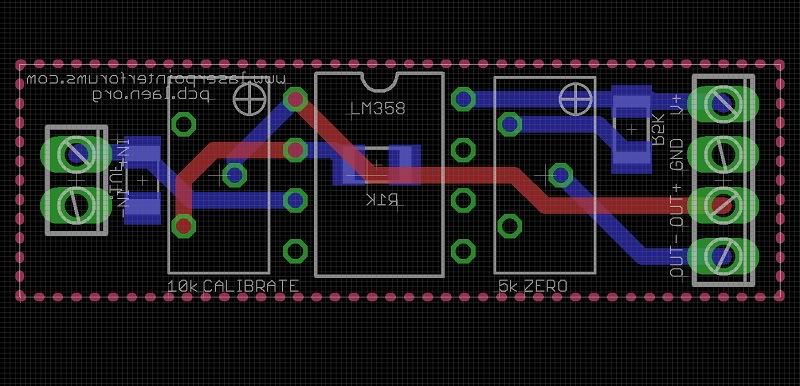
LPMbrd-1.jpg


Apart from the VIAs and the 2 red traces, is that really all the copper you have on the top side of your board? Is there still copper everywhere else on the top layer that is simply not connected to your traces?

Also, isn't it best to make use of copper plates as much as possible? I would assume just using traces would cause more noise? Especially regarding power and ground. When looking at PCB design files on this site generally all I see are just traces and not plates... why is that?

Anyone else care to chime in when its best to use a copper plate versus a trace?

What you are referring to are Ground Planes...
It is always a good idea to use ground planes
when dealing with extreme low level signals and
High gain amplifiers...

This circuit is not using extremely low level signals
and the amplifier has a marginal level of gain.

It would not hurt to put ground planes but the circuit
is simple enough to not really require it..

From the pics of the PCB in the 1st post it is obvious
that the PCB design IS using Ground Planes on both
sides of the PCB...

The reason you can't see them on the 2 sided Artwork
is if they were visible you couldn't see the traces easily...


Jerry
 
Last edited:


I'd almost say if he's using eagle cad (the most popular one for hobbyists) he might not have re-named the plane to ground hence the dotted line or he used some way of not showing it in the picture can't remember for sure though.

Also using ground planes are especialy nice if you are doing some tightly spaced parts and auto-trace can't get anything and manual tracing is giving you a hard time.
 
@ Benm

Also, the other differences and the main reasons that yours is more cheaper, they are.

The one you say is smaller 8 x 8 x 3.6 mm, the other is 8.4 x 8.4 x 2.3mm

Yours has a much lower number of Couples, only 7 couples (14 pellets, 7 N and 7 P), and this of Jufran88 has 31 Couples (62 pellets, 31 N and 31 P)

Apart from this, the voltage, amperage and temperature, which are also different in the 2 models, and this can be seen easily in the datasheets.

These difference are obvious indeed, perhaps i should have phrased it differently: Is there any good reason the cheaper TEC will perform less in this specific application?

I doubt the temperature maximum of 125 would be a problem unless you fire extremely powerful lasers at it. The number of junctions is another matter: does it greatly affect things like signal noise ratio, or is it just a matter of applying more amplification?
 
The Professional Thermopile heads like some Gentec and Scientec
heads use a special TEC that has a very high P/N thermocouple
junction count...
Here is a Gentec....

4959-thermopile1.jpg


It makes sense that the higher the count.... the more uniform the
active surface as wellas a higher signal level output...

That does not mean that the less expensive and lower junction cell
will not work...


Jerry
 
Last edited:
Whats the size of the Gentec TEC? You wouldn't have more pics of that?:D
Didn't know professional thermopiles just screw open so easy!
 
Last edited:
Sorry, got a question for you since i'm very new to PCB design.

When looking at
LPMbrd-1.jpg


Apart from the VIAs and the 2 red traces, is that really all the copper you have on the top side of your board? Is there still copper everywhere else on the top layer that is simply not connected to your traces?

Also, isn't it best to make use of copper plates as much as possible? I would assume just using traces would cause more noise? Especially regarding power and ground. When looking at PCB design files on this site generally all I see are just traces and not plates... why is that?

Anyone else care to chime in when its best to use a copper plate versus a trace?

Actually there are no vias on my PCB, Jib gave me the idea to use through hole pots to do away with the vias I previously had and the use of screw type connectors. They are really handy instead of soldering - desoldering - resoldering.

You can't see the ground planes on that picture because I didn't run the ratsnest when I took that picture. But if you look at the pics I took of the actual PCB you can easily see the ground planes aka "copper pour" areas.

If your etching your board by hand its a lot easier to leave more copper on the board and saves on etchant. They also make the board sturdier giving it more longevity and provides a better thermal relief due to high currents.

There are more technical reasons why the copper pour is important in PCB design because not only are they used to make power/ground planes but also provide EMI shielding for signal paths "traces". Isolation of the copper pour between traces, pads, holes becomes more important when high frequency/high current components are introduced. They create noise interference which can cause problems in some cases, that's why in some PCBs you see some areas of the circuits where there is no copper pour. I'm no PCB expert, but that's from my understanding so hopefully that helps?
 
@Benm, Sorry for the delay, I need to sleep and work a bit :)

Besides what Jerry said, who is the specialist,

IMHO the biggest problem can I see with your TEC is that it has a very small voltage range
(only 0.86 V), and with this simple LPM design, it can cause problems.

If the output of the TEC is larger, you need less gain from the op-amp,
and you have less noise and less error possibilities, that if you use a TEC with an output as low as yours.

Can it work? Is possible, but in my opinion not would choose your TEC for this LPM design.

Disadvantage of the other, well, is more expensive, yes, but worth it.

And the response time will be somewhat higher because of their greater mass
(have many more couples) but nothing to note.
 
Last edited:
I dont see a problem in the lower voltage itself - that could be amplified and compensated by a good opmap with a wide input range.

I am a but curious about what would be the most important factor in practical use: a sensor with fewer thermocouples would be faster, but one with more thermocouples could yield a better s/n ratio of the signal to measure.

Perhaps the only way to make sure is to give both a try.
 
What do you mean with thermistor, exactly ?

If PTC or NTC sensor, it's not enough sensitive ..... same for "bare" thermocouples, except if you find a way for connect 10 or 20 of them in serie (i tested 10 thermocouples junctions and a small piece of black anodized Alu, once, it was linear enough, but not sensitive, i had to amplify the serie like 400 times, and at this range, the noise was too high and interferring too much)

Also, a thermistor is not a differential device ..... if you want to use thermistors, you can buy a lot of SMD types NTC sensors (there are in 1mmx0.5mm sizes too) and connect like 20 or 30 of them in serie, glued rear a plate ..... but then, you need 2 plates of them, one as laser target, and the other near it, exposed to the same air flows and ambient temperature, but totally light insulated, for use as reference ..... otherwise, each time the ambient temperature change, also a fraction of degree, your unit become uncalibrated.

Same if you want to use diodes ..... there are SMD diodes with very small size, that you can connect in serie and glue rear a small plate, obtaining a sensor with a small (relatively small) mass, but still you need a reference sensor for ambient temperature.

Thermocouples thermopiles and TECs instead are differential sensors ..... they read the difference between the 2 plates, so as long as you provide a decent reference thermal mass (a big block of aluminium or copper, said in poor words :D) on the ref plate, once the thermal mass is stabilized with the ambient, the reading don't need to be continuously compensated from the ambient temperature.
 
Last edited:
Whats wrong with using a thermistor again?

Your question is a bit vague... What again...:thinking:
What exactly are you asking....:undecided:

If you are asking if you could use a thermistor as a Laser
Power Sensor..... Sure you can.... but as H9 explained...
one thermistor is not sensitive enough and you will always
need to a 2nd identical Thermistor as a reference...


Jerry
 
Last edited:
I dont see a problem in the lower voltage itself - that could be amplified and compensated by a good opmap with a wide input range.

I am a but curious about what would be the most important factor in practical use: a sensor with fewer thermocouples would be faster, but one with more thermocouples could yield a better s/n ratio of the signal to measure.

Perhaps the only way to make sure is to give both a try.


I dont see a problem in the lower voltage itself - that could be amplified and compensated by a good opmap with a wide input range.

Sure, but I'm talking about this simple LPM design in particular, I still say it would use the other TEC, but is my personal opinion.

but one with more thermocouples could yield a better s/n ratio of the signal to measure

That is what I refer.

Moreover, as you say it would be interesting to test the 2 models of TEC and see the results.
 
Nice build! Almost identical to mine, but a bit nicer looking on the interior (well, maybe?). I etched the board myself, and after playing around with the pots on both the panel and the board enough, I think I got it fairly well... reading good power outputs.
 
I finally had my LPM calibrated from a very reputable member here and it works awesome now!


Back
Top