Welcome to Laser Pointer Forums - discuss green laser pointers, blue laser pointers, and all types of lasers

LPF Donation via Stripe | LPF Donation - Other Methods

Links below open in new window

ArcticMyst Security by Avery

Making a porta-labby...Tutorial

Joined
Jun 12, 2008
Messages
1,199
Points
48
Hello,

I don't know if anyone will be/or is interested in making themselves a porta-labby, but I decided to do a tutorial for it anyway.

DISCLAIMER: Working with AC voltage can be hazardous to ones health, I take no responsibility if you house is filled by the smell of burning bacon.


Parts required:

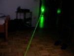
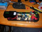
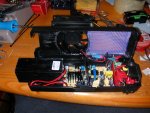
1x Labby with driver (I used the aixiz "50" mw labby)
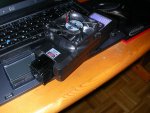
1x Fan shroud from a computer (was needed in my case due to the smaller size of used box)
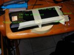
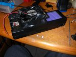
1x Plastic or any other box (really depends on what you have lying around and want to use, I used the box a cheap mag-lite mini rip-off)
1x Computer fan (again whatever you have lying around or want to use, mine was a 90x90mm fan taken from PSU)
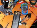
1x AC socket connector (salvaged from said PSU)
1x Switch (pretty much optional but I think it adds a cool touch, again salvaged mine from an old PSU)
1x Wires (yeah wires)
1x Old adapter to be gutted (PC fans nominally run at 12v, I have been running them at 5v for a while though, airflow is good and noise is decreased, so basically any adapter over the 5v output mark will do great for this mod, the one I am using is a 5v nokia adapter)
1x Some wire or plastic "net" (this was used to increase the airflow that the vent was sucking out of the module)

Tools required:

1x soldering iron
1x heatshrink (not absolutely necessary, but recomended)
1x dremel (hack saw and a file would also work, but it would require a lot more effort)
1x files (I have a set of assorted shapes, really helped smooth out the rough edges)
1x glue or hot glue-gun (whatever is lying around)


Building:

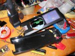
Ok now that we have all the parts and tools needed we can begin working on the project, it took me a good couple of hours to complete but I wasn't really in a hurry.
 

Attachments

  • DSCN0978.jpg
    DSCN0978.jpg
    215.9 KB · Views: 206


Joined
Jun 12, 2008
Messages
1,199
Points
48
I started by measuring the size of my host and determining how the components will be placed in order to maximize the cooling efficiency. Once I had come up with a layout that I was satisfied with I marked where the fan shroud will be placed, where the connector/switch will be located, where the net will be placed and where the module will stick out.

Your results or layout might/will be very different from mine due to the fact that your box/host might be a bit bigger or even smaller.


Once you are finished with all the cutting and filing, the electrical/fun part can begin.
 

Attachments

  • DSCN0979.jpg
    DSCN0979.jpg
    118.9 KB · Views: 165
Joined
Jun 12, 2008
Messages
1,199
Points
48
Once we have the host ready and completed, the fan mounting and net placement can begin.

The fan shroud from the computer was way too tall for my needs which is why it was cut down to be flush with the host. Don't cut it down all in swoop! Cut it gradually (its soft anyway), and check fitments/positioning every time you cut, so that you get the perfect layout for your project.

Once you are finished with the fan shroud and are satisfied with the way it is mounted on the host, leave it be do not glue as there might be complications with clearance and wire placement later on in the build.

For this project I used a hot-glue gun, for such fitments later on.

Now we are onto the net part. For this I used some netting salvaged from an old computer case, (it is/was used to keep the dust out, making it perfect for the project).

Start on one side of the rectangle and generously apply the molten glue to lock it in place. Now stretch it to the adjacent side while keeping it tight, hot glue here as well. Continue with this process and you will have a nice toight net to keep the dust out and maintain a good cooling ability.

Here is what my host looked like after this process. Notice the hole prepared for the switch.

Now we can start with the electronic aspect of the tutorial.
 

Attachments

  • DSCN0980.jpg
    DSCN0980.jpg
    145.1 KB · Views: 154
Joined
Jun 12, 2008
Messages
1,199
Points
48
I started the electrical part by installing the switch and mains connector. (The mains connector nor the switch are required, but the ability to carry the labby around without 4 feet of heavy cable is an added bonus, plus everyone has the required mains cable, if not standing by then it is in use in their computer)

The mains connector was simply screwed in place while the switch popped right in.

The wiring is really not too complex:

-one wire is neutral while the other is the live conductor, since its AC, it doesn't really matter, however for schnits and giggles I treated neutral as ground, don't ask me why I wont be able to tell you.

I think that the wiring up until this point is pretty self-explanatory but if anyone has a question/is interested feel free to ask.
 

Attachments

  • DSCN0981.jpg
    DSCN0981.jpg
    190.4 KB · Views: 132
Joined
Jun 12, 2008
Messages
1,199
Points
48
Component placement and final wiring.

Ok now that we have placed all components securely (i used double sided foam tape for driver and adaptor), we can pretty much finalize the wiring. The more vigilant of you will notice that I used a different adapter board for the final design than I initially intended, well this is because I busted the old one up shrink-wrapping it, I went was to crazy with the stuff and snapped the legs of two caps, and easy fix, but I wasn't in the mood, so I just ripped apart another nokia adaptor and continued working.

The was I wired was:

Neutral from mains to the adapter lead (was an on-die lead no cable).

live conductor to the other adapter lead.

After temporarily isolating the connections, I proceeded to test the adapter board output, with no load a cool 6v.

The next step was to install the driver board.

After, taping it in place (really strong double sided tape), I connected it the leads on the adapter board. (well to the cables leading to the board, but its pretty much the same thing,) your placement and installation may vary depending on the adapter board you will be using.

That pretty much concludes the soldering part of the tutorial.


Here is a picture of placement:
 

Attachments

  • DSCN0982.jpg
    DSCN0982.jpg
    176.8 KB · Views: 138
Joined
Jun 12, 2008
Messages
1,199
Points
48
Ok so that wasn't the last if the soldering: hehe

Now that we have both bottom and top halves of the project completed they must be joined. I order for me to get a semi-clean looking porta-labby, the holes for the fan wires had to be drilled. A bit of an indent in the fan shroud right be where the wires come out of the fan and the place where it connects to the host is required.


Now all that we have to do is connect and insulate the fan wires. And we are about done.
 

Attachments

  • DSCN0983.jpg
    DSCN0983.jpg
    173.7 KB · Views: 151
Joined
Jun 12, 2008
Messages
1,199
Points
48
Here is the finished project:


I think that it kind of looks like a baby argon head...? :)

Oh and don't mind the dirt and dust, it looks much nicer without the flash.


I hope that this tutorial was made clearly and will be helpful to those of you not using your labby in a scanner. It might be a bit on the no duh (dude its obvious) side, but I decided to make it in anyway, to in a small way give something back to the community which ha provided me with a huge amount of knowledge from members and other tutorials, priceless.

If anyone has a question about any part feel free to ask.


brtaman
 

Attachments

  • DSCN0984.jpg
    DSCN0984.jpg
    151.8 KB · Views: 203
Joined
Jun 12, 2008
Messages
1,199
Points
48
Oh yeah almost forgot the obligatory beam shot: ;D
 

Attachments

  • DSCN0988.jpg
    DSCN0988.jpg
    73.7 KB · Views: 158
Joined
Jun 12, 2008
Messages
1,199
Points
48
Hey man,

Thanks!

Being an owner of an argon laser, what is your opinion, doesn't it look a tad like a baby argon?


brtman
 

daguin

0
Joined
Mar 29, 2008
Messages
15,989
Points
113
brtaman said:
Hey man,
Thanks!
Being an owner of an argon laser, what is your opinion, doesn't it look a tad like a baby argon?
brtman

It looks like Mini-Frakenstien's mini argon ;D ;D ;D

Nicely done!!

Maybe a smaller fan, but beyond that +1 for bringing your creative idea to life

IT LIVES!!!!!

Peace,
dave
 
Joined
Jun 12, 2008
Messages
1,199
Points
48
daguin said:
[quote author=brtaman link=1215854778/0#9 date=1215869474]Hey man,
Thanks!
Being an owner of an argon laser, what is your opinion, doesn't it look a tad like a baby argon?
brtman

It looks like Mini-Frakenstien's mini argon ;D ;D ;D

Nicely done!!

Maybe a smaller fan, but beyond that +1 for bringing your creative idea to life

IT LIVES!!!!!

Peace,
dave


[/quote]


Hehe, now that you mention it, maybe I should paint it green and stick bolts on the side :) and a speaker so that when I start it up it makes a frankenstein growl ;D Now that you mention it though the driver and the adapter electronics are really loud it actually does sound like something dr. frankenstein would cook up.

Nice wording on the bringing the idea to life part hehe

Thanks for the rep though, much appreciated!


brtaman
 

alf638

0
Joined
Dec 10, 2010
Messages
218
Points
0
It really does look lalot like my argon.
+1 for a great build.


Top