Welcome to Laser Pointer Forums - discuss green laser pointers, blue laser pointers, and all types of lasers

LPF Donation via Stripe | LPF Donation - Other Methods

Links below open in new window

ArcticMyst Security by Avery

LPM circuit

Joined
May 17, 2014
Messages
9
Points
0
I have designed an lpm circuit on bases of this:

LPMschem.jpg


Can anyone tell me if this circuit is correct and will it work ?????

image.png
 
Last edited:


ARG

0
Joined
Feb 27, 2011
Messages
6,772
Points
113
Those pot footprints don't look like multi-turn pots. You'll want one for the 10k calib pot.
 

ARG

0
Joined
Feb 27, 2011
Messages
6,772
Points
113
A or B does not really matter IMO.


For the unused op amp you should tie the -IN to the output and the +In to common. It will rail the op amp low so that it does not cause noise, as the way you have it will rail it in an unknown state cause noise.
 
Last edited:
Joined
May 17, 2014
Messages
9
Points
0
Hey ARG i am kinda noob to it so can you explain it on the circuit via some lines. I will be very thankful to you :)
 
Joined
May 17, 2014
Messages
9
Points
0
By Juffran88
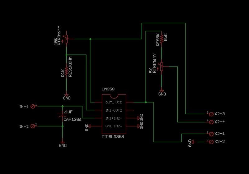
This is actually my second attempt at this since my first one didn't work so well. My first attempt failed because of an improper connection made on the second (unused) op-amp on the LM358.

opampwrong.jpg


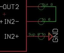
I first had the unused op-amp with one input to GND and the output feed back into the other input like this:


That didn't work and actually made the IC extremely hot and readings fluctuated erratically. I gave up after that failed try, but after a month or so the topic came up and a few members helped me out. It seems that a dual op-amp IC like the LM358 won't work correctly since both op-amps feed from the same power supply, but would work with a single op-amp IC.
http://laserpointerforums.com/f42/my-diy-laser-power-meter-pic-heavy-64947.html

I am kind of confused what to do :)
 
Last edited:


Top