Jufran88
0
- Joined
- Feb 9, 2011
- Messages
- 578
- Points
- 0
My DIY Laser Power Meter
I want to introduce you guys to my recent build. I have been working on this off and on for a few months now. The circuit is based off MarioMaster from his thread with all the parts and components needed listed there: http://laserpointerforums.com/f42/diy-thermal-lpm-under-50-a-51129.html
This is actually my second attempt at this since my first one didn't work so well. My first attempt failed because of an improper connection made on the second (unused) op-amp on the LM358.
I first had the unused op-amp with one input to GND and the output feed back into the other input like this:
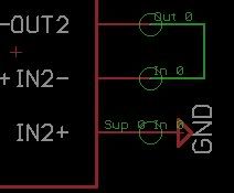
That didn't work and actually made the IC extremely hot and readings fluctuated erratically. I gave up after that failed try, but after a month or so the topic came up and a few members helped me out. It seems that a dual op-amp IC like the LM358 won't work correctly since both op-amps feed from the same power supply, but would work with a single op-amp IC.
So after some revision here is the final schematic:
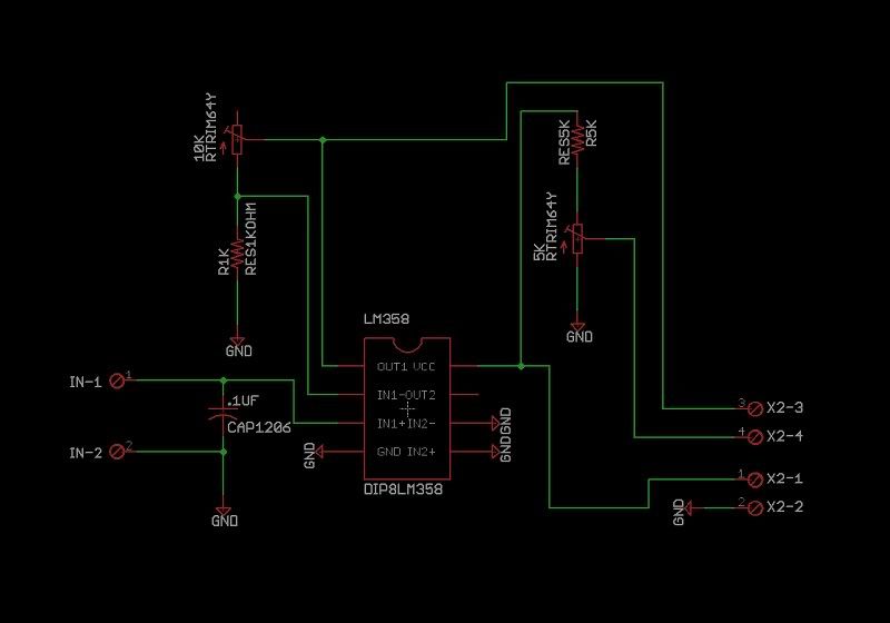
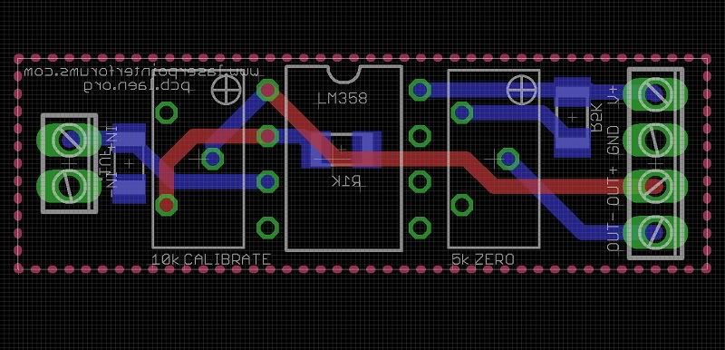
Final board:
*not all connections are seen because they are connected to the ground plane*
Acutal board (front):
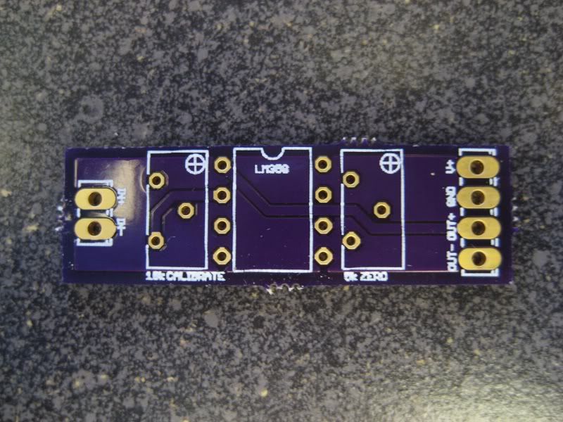
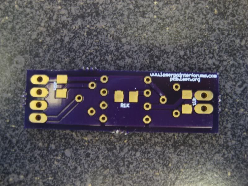
Actual board (back):
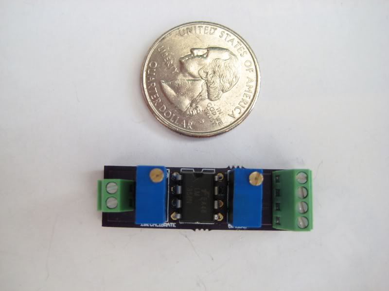
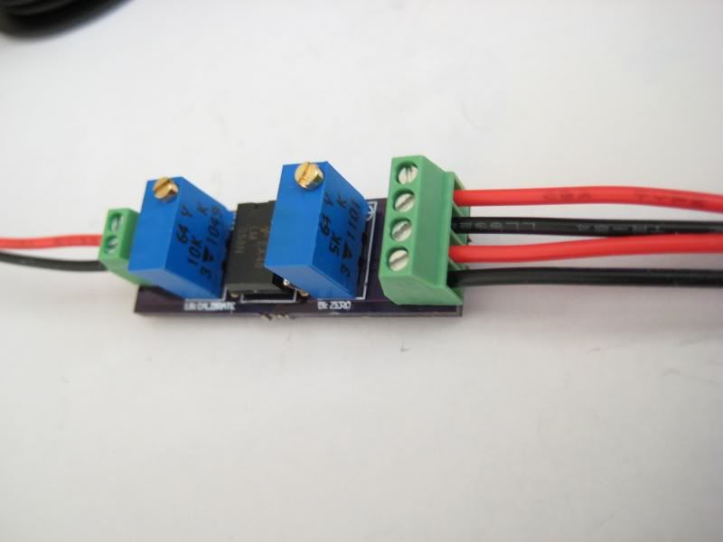
Board all components soldered:
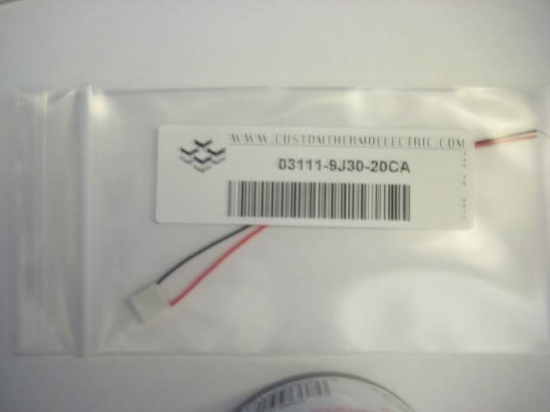
8x8 mm TEC:
8x8 mm TEC (uncoated):
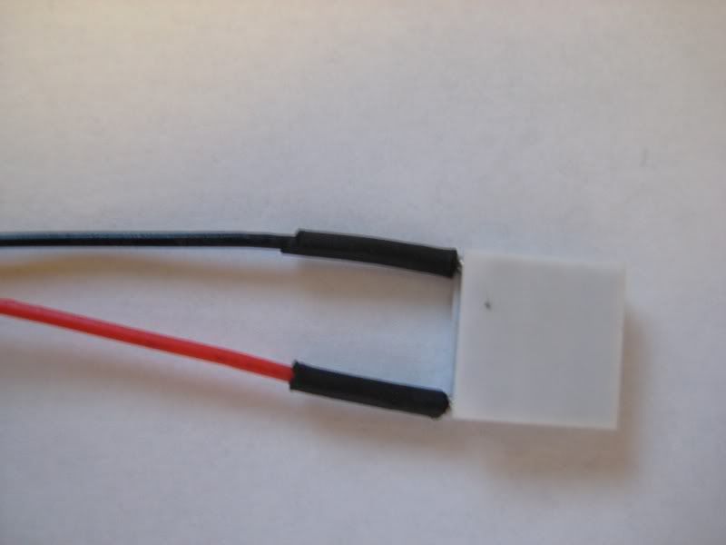
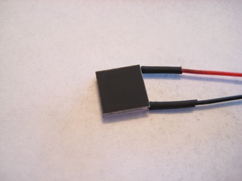
8x8 mm TEC (coated):
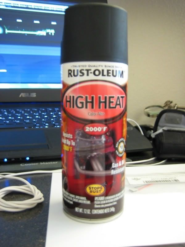
Paint used (Rust-O-Leum high heat flat black):
*It's important to use a non glossy paint most of the beam is absorbed*
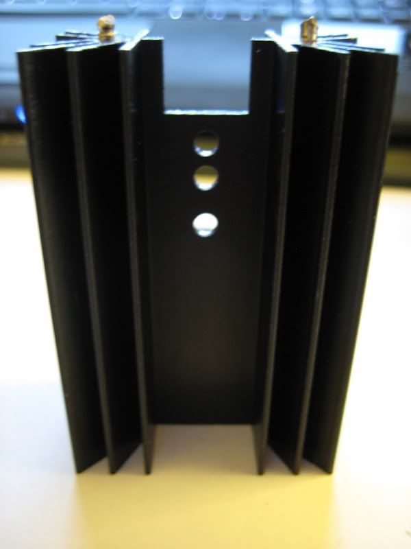
Heatsink used:
Digi-Key - EA-T220-64E-ND (Manufacturer - EA-T220-64E)
Heatsink with TEC thermal pasted on:
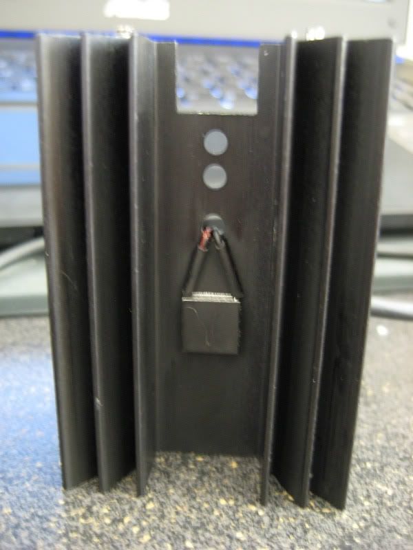
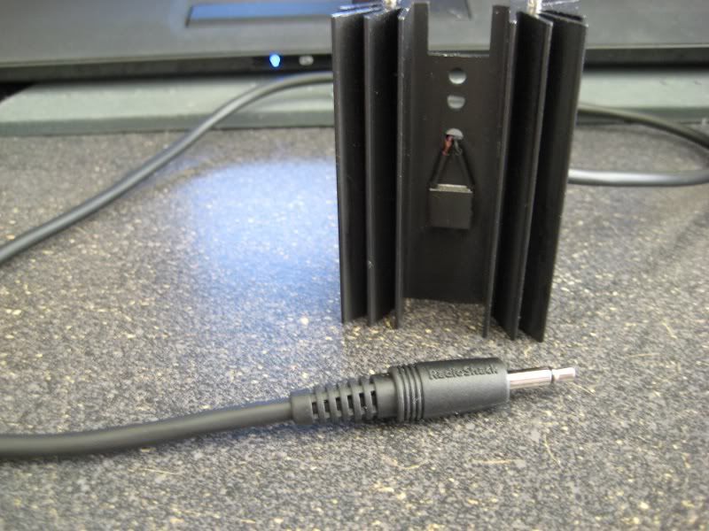
Heatsink with 1/8 plug cable attached:
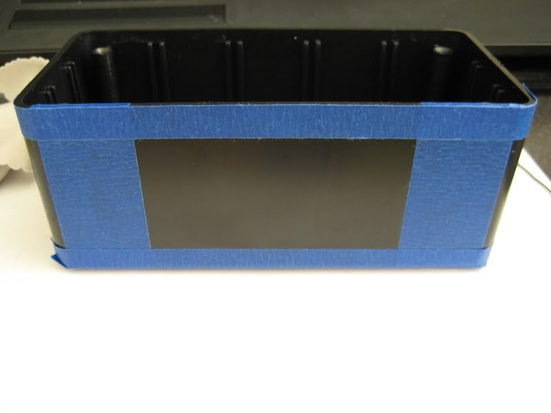
Project box (6x2.5x2):
*taped up and ready to be cut :yh:*
Project box cut with volt panel meter unassembled:
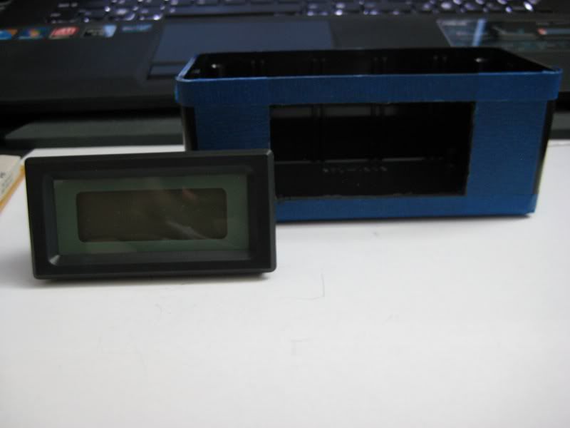
3 1/2 digit volt panel meter:
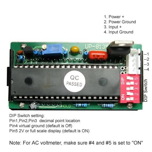
Switch being mounted:
*I used a DPST (double pole single throw) switch to connect both the volt panel meter and amplifier circuit*
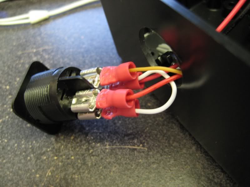
Inside box:
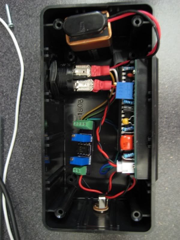
1/8 plug jack:
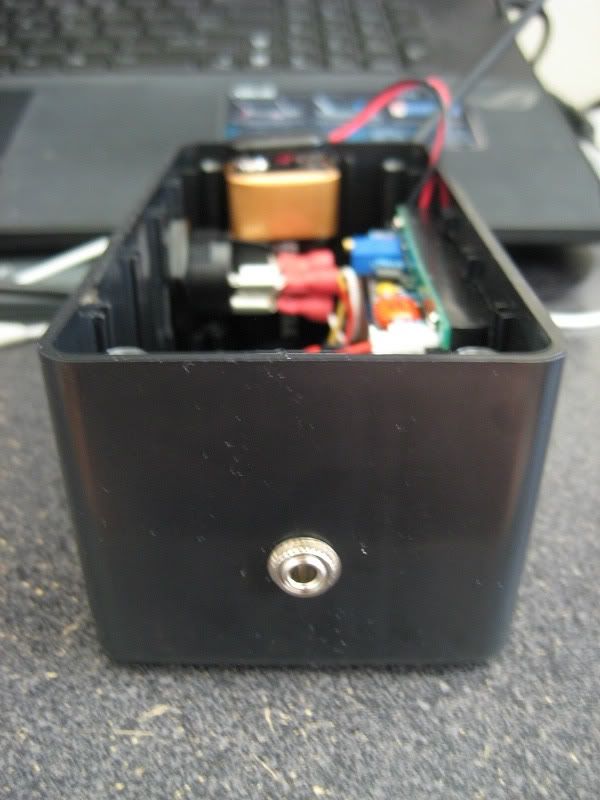
Mounted switch:
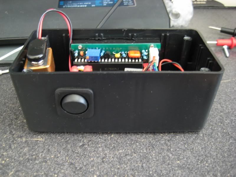
Completed LPM (off):
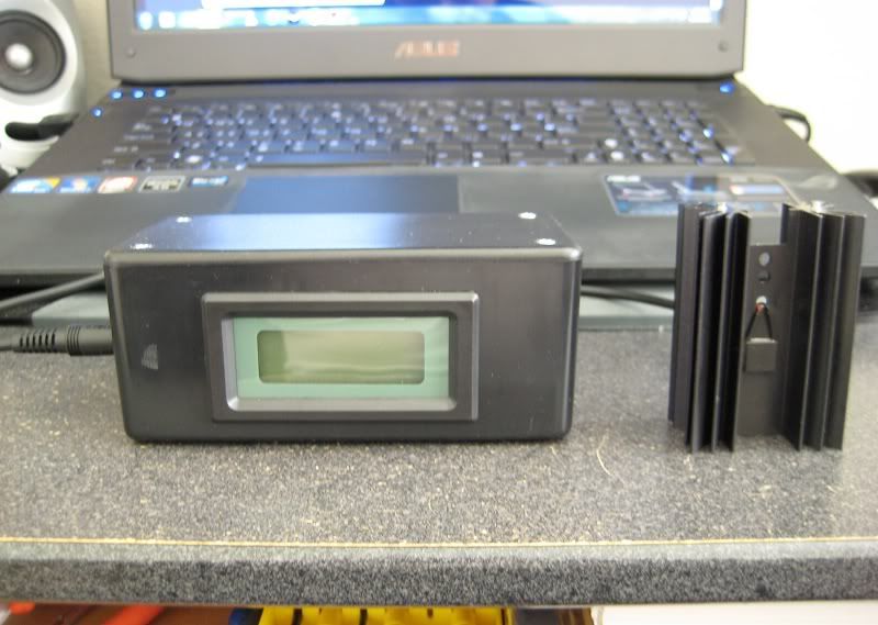
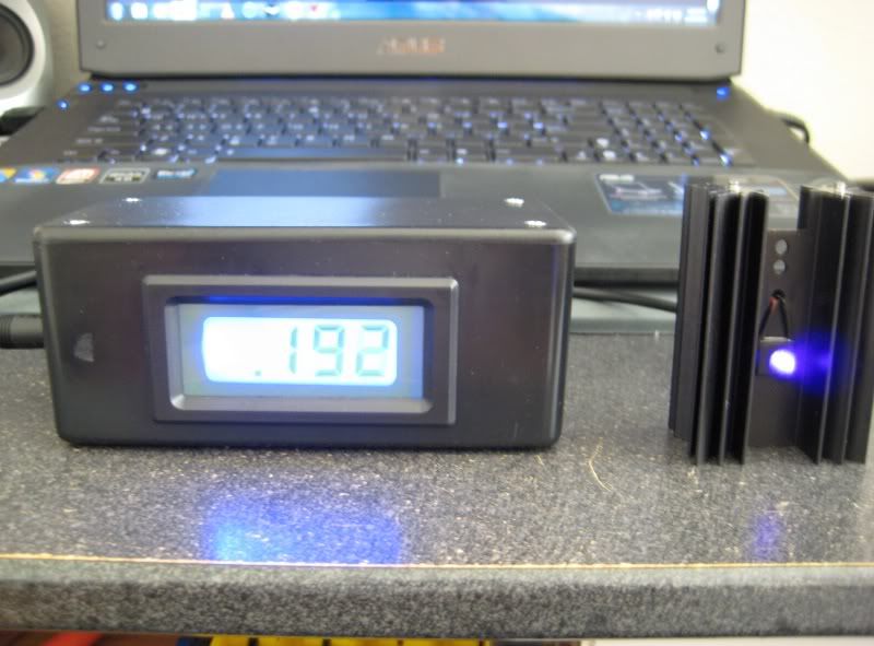
Completed LPM (on):
*Ignore LPM output value because it's not calibrated yet*
Videos:
Off/on:
Sample metering:
Final thoughts:
Overall I'm pleased with the outcome. However, there are just a few things that bothered me. It will do for the time being until I buy a credible LPM. I think I spent about 60-80 dollars total for this build.
1. When I attempted to zero my meter it will not go to zero! It will only set at -.011V. I tried using my multimeter and it zeros fine. So it might be the panel meter having the problem.
2. When I try to calibrate for the power output it does not want to go down lower than .194V because I know for sure my PHR-803T isn't outputting over 200mW, unless its a freak diode. I highly doubt it because I tried metering my 445nm and it wont go down less than 2W.
3. I accidentally nicked the front of my LPM box with my dremel as I cut the hole for the panel meter. Not a big deal, but I like my things spotless
:thanks: for looking!
Any questions, comments, concerns feel free to post.
I want to introduce you guys to my recent build. I have been working on this off and on for a few months now. The circuit is based off MarioMaster from his thread with all the parts and components needed listed there: http://laserpointerforums.com/f42/diy-thermal-lpm-under-50-a-51129.html
This is actually my second attempt at this since my first one didn't work so well. My first attempt failed because of an improper connection made on the second (unused) op-amp on the LM358.
I first had the unused op-amp with one input to GND and the output feed back into the other input like this:

That didn't work and actually made the IC extremely hot and readings fluctuated erratically. I gave up after that failed try, but after a month or so the topic came up and a few members helped me out. It seems that a dual op-amp IC like the LM358 won't work correctly since both op-amps feed from the same power supply, but would work with a single op-amp IC.
So after some revision here is the final schematic:

Final board:
*not all connections are seen because they are connected to the ground plane*

Acutal board (front):

Actual board (back):

Board all components soldered:


8x8 mm TEC:

8x8 mm TEC (uncoated):

8x8 mm TEC (coated):

Paint used (Rust-O-Leum high heat flat black):
*It's important to use a non glossy paint most of the beam is absorbed*

Heatsink used:
Digi-Key - EA-T220-64E-ND (Manufacturer - EA-T220-64E)

Heatsink with TEC thermal pasted on:

Heatsink with 1/8 plug cable attached:

Project box (6x2.5x2):
*taped up and ready to be cut :yh:*

Project box cut with volt panel meter unassembled:

3 1/2 digit volt panel meter:

Switch being mounted:
*I used a DPST (double pole single throw) switch to connect both the volt panel meter and amplifier circuit*

Inside box:

1/8 plug jack:

Mounted switch:

Completed LPM (off):

Completed LPM (on):
*Ignore LPM output value because it's not calibrated yet*

Videos:
Off/on:
Sample metering:
Final thoughts:
Overall I'm pleased with the outcome. However, there are just a few things that bothered me. It will do for the time being until I buy a credible LPM. I think I spent about 60-80 dollars total for this build.
1. When I attempted to zero my meter it will not go to zero! It will only set at -.011V.
2. When I try to calibrate for the power output it does not want to go down lower than .194V because I know for sure my PHR-803T isn't outputting over 200mW, unless its a freak diode. I highly doubt it because I tried metering my 445nm and it wont go down less than 2W.
3. I accidentally nicked the front of my LPM box with my dremel as I cut the hole for the panel meter. Not a big deal, but I like my things spotless
:thanks: for looking!
Any questions, comments, concerns feel free to post.
Last edited:


