Immo1282
0
- Joined
- Sep 4, 2018
- Messages
- 562
- Points
- 63
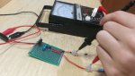
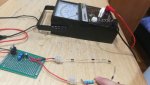
A shunt resistor is just a normal resistor being used for the purpose of measuring the current in a given circuit.


Follow along with the video below to see how to install our site as a web app on your home screen.
Note: This feature may not be available in some browsers.


")
A shunt is just a parallel circuit. This means that your shunt resistor is parallel to something else.....in this case, the meter.A shunt resistor is just a normal resistor being used for the purpose of measuring the current in a given circuit.
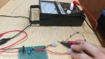
having to factor in the loading of a moving-coil voltmeter into your measurements may not be helping you so much...